background image

EN 

27

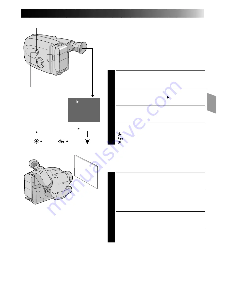
M.W.B.

MWB

No indication (Auto)

MWB

White balance
mode indicator

SELECT

PROGRAM AE select dial

SET

Manual White Balance Adjustment (M.W.B.)

This camcorder’s Automatic Colour Temperature system
senses the colour temperature of the ambient lighting for
automatic white balance adjustment. However, precise
colour adjustment is not possible under the following
conditions:

• When an object is in various shades of the same colour.
• When a predominantly red or brown object is being shot

outdoors.

In these cases, use the camcorder’s built-in preset filters for
white balance adjustment.

SELECT MODE

1

Turn the PROGRAM AE select dial to any position
except AUTO LOCK.

SELECT FUNCTION

2

Press SELECT reapeatedly until “

M.W.B.

” appears.

SELECT WHITE BALANCE

3

Press SET (Manual White Balance) until the required
indication appears in the viewfinder.

“MWB” ..... With a memorized personal White Balance

setting (see below)

” ......... Outdoors on sunny day

”......... Outdoors on cloudy day

” .......... Light source is halogen or tungsten lamp

MWB

MWB sets the colour temperature for the subject’s light
source so you can shoot with natural colours that are
unaffected by surroundings, even when there are multiple
subjects with different colour temperatures.

SELECT MODE

1

Turn the PROGRAM AE select dial to any position
except AUTO LOCK.

ADJUST FOCUS

2

Point the camcorder at a white, flat object such as a
sheet of white paper, and adjust focus manually
(

Z

 pg. 19).

ADJUST WHITE BALANCE

3

Press SET until “MWB” appears, then press and hold
SET for more than 3 seconds.

• “MWB” blinks in the viewfinder during adjustment,

then stops blinking but stays lit when adjustment is
complete.

NOTES:

To switch to automatic white balance adjustment, press SET until the indication disappears, or turn the PROGRAM AE
select dial to “AUTO LOCK”.

Re-adjust the White Balance when the lighting has changed, when the camcorder has been turned off and on again, or
when the PROGRAM AE select dial’s position has been changed.

It is helpful to connect your camcorder to a colour monitor when adjusting the white balance (“Basic Connections”

Z

 pg. 30).

When adjusted by putting coloured paper in front of the subject in step 2 (“ADJUST FOCUS”), this unit makes its colour
temperature standard for automatic white balance. So you can enjoy shooting with different colours. For example, when
adjusting with red, blue or yellow colours, the image becomes the colour which aproximates to green, orange or purple
respectively.

Summary of Contents for GR-SZ7000

Page 1: ...GR SZ7000 COMPACT VHS CAMCORDER LYT0002 0A3A INSTRUCTIONS ENGLISH EN Super VHS VHS PAL 625 ...

Page 2: ...adapter may be necessary to accommodate different designs of AC outlets in different countries NOTES The rating plate serial number plate and safety caution are on the bottom and or the back of the main unit The rating plate serial number plate of the AC Power Adapter Charger is on its bottom This unit is produced to comply with Standard IEC Publ 65 2EN 625 PAL Using This Instruction Manual All ma...

Page 3: ...INDEX 48 Controls 48 Connectors 49 Indicators 49 Other Parts 49 Viewfinder 50 CAUTIONS 51 SPECIFICATIONS 53 GETTING STARTED RECORDING PLAYBACK EDITING n Program Manager Z pg 16 29 n Programme AE with Special Effects Z pgs 16 17 Auto Mode Lock Auto Mode Release 180X Digital Zoom Strobe Classic Film Twilight Sports Slow Shutter 1 2000 sec High Speed Shutter n Picture Stabilizer Z pg 20 n Digital Hyp...

Page 4: ...tion of the arrow To AC outlet BATT PACK CHARGE DISCHARGE BN V12U approx 1 hr 10 min approx 3 hrs 30 min BN V22U approx 2 hrs 10 min approx 7 hrs BN V25U approx 2 hrs 40 min approx 10 hrs USING THE BATTERY PACK ATTACH BATTERY PACK 1 Hook its top end to the camcorder and push the battery pack in until it locks in place DETACH BATTERY PACK 2 Slide BATT RELEASE and pull out the battery pack Charge ma...

Page 5: ...discharging the battery pack A blinking CHG indicator means that the battery pack has become hot Wait until it cools down to continue The CHG indicator may not light properly with a brand new battery pack or with one that s been stored for an extended period In this case remove and reattach the battery pack and recharge it The CHG indicator should light during recharging If not contact your neares...

Page 6: ...nd the compartment A and pull the battery out INSERT BATTERY 4 Ensuring the plus side is up insert a CR2025 lithium battery and push it in CLOSE COVER 5 Close the compartment cover until it clicks in place NOTE See SAFETY PRECAUTIONS Z pg 2 for information on safe handling of lithium batteries Viewfinder Adjustment POSITION VIEWFINDER 1 Adjust the viewfinder manually for best viewability see illus...

Page 7: ... you decide you want to return the date and time to the previous settings press FAR or NEAR to move the highlight bar to Cancel then press MENU If you re satisfied with the settings go on to step 5 START CLOCK OPERATION 5 Once you ve set the date and time press FAR or NEAR until Set begins to blink then press MENU The Menu screen reappears CLOSE MENU 6 Press MENU NOTES To display the date and time...

Page 8: ...quired indication appears in the viewfinder Super VHS T Regular VHS NOTE Super VHS recordings cannot be made on VHS C tapes S VHS VCR Regular VHS VCR COMPATIBILITY BETWEEN S VHS AND VHS Recording Playback Recorded tape Camcorder Blank tape Cassette adapter S VHS C cassette VHS recordings VHS C cassette The recorded format S VHS or VHS is automatically detected when playlback begins S VHS recorded ...

Page 9: ... a power supply is attached Make sure that the tape is not slack when loading the cassette If there is any slack turn the gear on the cassette in the direction of the arrow to take up the slack Make sure the Erase Protection tab is in the position that allows recording If not slide the tab Some cassettes have removable tabs If the tab has been removed cover the hole with adhesive tape The cassette...

Page 10: ...rough the top of the eyelet 1 then fold it back and thread it through the keeper 2 and then through the buckle 3 Repeat the procedure to attach the other end of the strap to the other eyelet making sure the strap isn t twisted ADJUST LENGTH 2 Adjust as shown in the illustration at left 1 then slide both keepers snug against the eyelets to prevent slipping 2 Tripod Mounting ALIGN AND TIGHTEN 1 Alig...

Page 11: ... cassette holder can t be opened unless a power supply is attached There may be a delay after you slide EJECT until the holder opens Do not use force The tape s remaining time is displayed in the viewfinder as shown The indicated remaining time is approximate The time required to calculate the remaining tape length and the accuracy of the calculation may vary according to the type of tape used The...

Page 12: ... pg 18 19 then zoom in or out in Record mode The Zoom Level Indicator 5 only moves during optical zoom Once the Zoom Level indicator reaches the top of the zoom indicator bar all magnification from that point is through digital processing During digital image processing the quality of the image may suffer Snapshot Z pg 14 Dissolve and Auto Select in Fade Wipe Z pg 23 do not function when Programme...

Page 13: ... AUTO PAUSE so that APS ON appears in the viewfinder for 2 seconds When the camcorder is tilted down by a large degree from its horizontal position during recording the Record Standby mode is automatically engaged During this AUTO is displayed above PAUSE To switch off the Auto Pause System press AUTO PAUSE again so that APS OFF appears in the viewfinder for 2 seconds NOTES The Auto Pause System i...

Page 14: ...ected and activated and its indicator appears within 2 seconds PERFORM SNAPSHOT RECORDING 2 Press SNAPSHOT If you press during recording a still image is displayed and recorded in the selected mode then the camcorder resumes normal recording In the Full and Frame modes the new image comes in gradually overall In the Pin Up and Multi Analyzer modes the new image comes in gradually from the center I...

Page 15: ... or when you start recording with the video light turned on When the LIGHT OFF AUTO ON switch is set to AUTO Depending on the lighting conditions the video light may keep turning on and off In this case manually switch the light on or off using the LIGHT OFF AUTO ON switch While the Sports or High Speed Shutter mode Z pg 17 is engaged the light is likely to stay on While the Twilight mode Z pg 17 ...

Page 16: ...e mode is activated When Auto Mode Lock or Auto Mode Release mode is selected only the mode s name is displayed Then the name disappears and the mode is activated NOTES Only one effect can be engaged at a time The screen becomes slightly dark in the High Speed Shutter mode Use in well lighted situations In the High Speed Shutter or Sports modes picture colour may be adversely affected if subject i...

Page 17: ...en the subject to camera distance is less than 10 m use manual focusing Z pg 19 DIAL VIEWFINDER MODE SYMBOL INDICATION Slow Shutter Sets the shutter speed to 1 12 5 sec and boosts the sensitivity so that the camcorder can record subjects even in virtual darkness Use it only in dark locations The picture flickers like a quick strobe Sports High shutter speed clearly captures fast moving action High...

Page 18: ... the camcorder Engage the focus lock function to lock your subject in before recording When you want your subject to be focused and to appear in a corner of the screen First center on the subject and focus using auto focus mode Then engage the focus lock function and move the camcorder until the subject is where you want it SELECT MODE 1 Turn the PROGRAM AE select dial to any position except AUTO ...

Page 19: ...AR or NEAR The focus indication is replaced by the focus lock indication and the adjusted focus is locked in RELEASE MANUAL FOCUS MODE 4 Press FAR and NEAR simultaneously The Manual Focus mode is immediately released and the focus lock indication disappears NOTES Be sure to focus the lens in the maximum telephoto position when you use the Manual Focus mode If you focus in on a certain subject in t...

Page 20: ... or under the following conditions When shooting subjects with vertical or horizontal stripes When shooting dark or dim subjects When shooting subjects with excessive backlighting When shooting scenes with movement in various directions When shooting scenes with low contrast backgrounds When the Slow Shutter function is activated Z pg 17 the Picture Stabilizer cannot be used If you try to activate...

Page 21: ...RAM AE select dial to any position except AUTO LOCK BRIGHTEN IMAGE 2 Press maximum 06 The Exposure level indicator appears in the viewfinder OR DARKEN IMAGE Press maximum 06 The Exposure level indicator appears in the viewfinder When you want to return to the factory setting RESTORE INITIAL SETTING 3 Press and simultaneously The standard setting is immediately restored and the Exposure level indic...

Page 22: ...s selected and reserved The selected mode s name and its indication are displayed in the viewfinder for approx 2 seconds Then the name disappears and only the indication remains START RECORDING 4 Press Recording Start Stop to start recording and activate fade or wipe in OR END RECORDING Press Recording Start Stop to end recording and engage fade or wipe out TO CANCEL FADE OR WIPE STANDBY MODE 5 Wh...

Page 23: ...Stop button again Recording stops and the Record Standby mode is engaged Now the last scene is stored in memory 3 Press the Recording Start Stop button to resume recording The stored scene is gradually replaced by the new scene being shot SCROLL WIPE AUTO SELECT only A new image scrolls up onto the screen WINDOW WIPE AUTO SELECT only A new image enters from the centre and moves towards the corners...

Page 24: ...ESTORE NORMAL SCREEN 4 Press SET again while Wide appears Instant Titles The camcorder has eight preset titles in memory You can superimpose one of them above a previously stored title as shown in the illustration to the left DISPLAY SELECT MODE 1 Turn the PROGRAM AE select dial to any position except AUTO LOCK SELECT FUNCTION 2 Press SELECT repeatedly until Title appears SELECT PRESET TITLE 3 Eng...

Page 25: ...4 Press FAR or NEAR to make End blink then press MENU twice to return to the normal screen NOTES To erase a character you entered mistakenly make Clear blink by pressing FAR or NEAR then press MENU All characters are deleted at once Or to erase selected characters only first move the blinking cursor to the character at the bottom row which you want to replace then press FAR or NEAR to highlight in...

Page 26: ... recall the display press SET again AUTO DATE RECORD Your camcorder automatically records the date for about 5 seconds after recording is initiated in the following situations After changing the date After loading a cassette After Auto Date Record mode is selected by pressing SET In this mode the date is replaced after 5 seconds with Auto Date NOTES Setting PROGRAM AE to LOCK always engages the Au...

Page 27: ...cted by surroundings even when there are multiple subjects with different colour temperatures SELECT MODE 1 Turn the PROGRAM AE select dial to any position except AUTO LOCK ADJUST FOCUS 2 Point the camcorder at a white flat object such as a sheet of white paper and adjust focus manually Z pg 19 ADJUST WHITE BALANCE 3 Press SET until MWB appears then press and hold SET for more than 3 seconds MWB b...

Page 28: ...2 Press MENU SELECT FUNCTION 3 Press or to place the highlight bar on the desired function MAKE SETTING 4 The setting procedure depends on the function you select If you select Gain Up Tele Macro Interval Timer Rec Time JLIP ID NO or Tally press FAR or NEAR to cycle through the choices until the desired setting appears If you select Set Character or Date Time press NEAR to access the selection men...

Page 29: ...ition the lens may go out of focus Interval Timer This feature allows you to set the parameters for Self Timer Z pg 30 and Time Lapse recording Z pg 31 Rec Time This feature allows you to set the parameters for Animation and Time Lapse recording Z pg 31 JLIP ID NO This number is necessary when connecting the camcorder to a device such as a computer using the J terminal JLIP Z pg 49 The numbers ran...

Page 30: ...AR to cycle through the choices Stop when the desired time appears Choose from 15s 30s 1min 5min or select to turn the function OFF CLOSE MENU 3 Press MENU START DELAYED RECORDING 4 Press Recording Start Stop The tally lamp begins blinking and the blinking frequency increases about 5 seconds before recording is to start Once recording begins the lamp stops blinking but stays lit To Release Self Ti...

Page 31: ...ng Animation or Time Lapse recording make sure the Animation or Time Lapse mode is deactivated Time Lapse You can record sequentially at preset time spans Leaving the camcorder aimed at a specific subject you can record subtle changes over an extended period of time NOTE Make sure the camcorder is in the Record Standby mode before performing the following steps ACCESS MENU SCREEN 1 Turn the PROGRA...

Page 32: ...ow not connect To S VIDEO OUT S VIDEO cable provided TV VCR B Connection To a TV or VCR equipped with a SCART connector compatible with Y C signal To S IN jack cover Red to AUDIO R White to AUDIO L White to AUDIO L in Red to AUDIO R in TV VCR To TV or VCR C Connection To a TV or VCR equipped with an S VIDEO IN and or A V input RCA type connectors To S VIDEO OUT To S VIDEO IN A V cable provided S V...

Page 33: ...erence will occur in the camcorder playback picture A Connection to a TV or VCR equipped with a SCART connector compatible only with regular video signals NOTE Use the provided A V cable and cable adapter CONNECT CAMCORDER TO TV VCR 1 As shown in the illustration at left connect the A V cable to the AUDIO and VIDEO connectors on the camcorder and to those on the cable adapter and then connect the ...

Page 34: ...t 5 minutes in Stop mode or Still Playback mode To turn on again set the Power switch to POWER OFF then to PLAY Select the Audio Playback Soundtrack Press the Hi Fi MIX NORMAL audio output select button so that the required indication appears in the viewfinder HiFi Outputs Hi Fi stereo sound from the AUDIO OUT connectors Use this setting for normal use Mix Outputs both Hi Fi stereo sound and longi...

Page 35: ...ttle Search PURPOSE To allow high speed search in either direction OPERATION Forward Search 1 Press FF during playback Reverse Search 1 Press REW during playback NOTE Noise bars appear and pictures may become monochrome or darken in Shuttle Search This is normal FEATURE Counter Memory Function PURPOSE To make it easier to locate a specific tape segment OPERATION 1 Press COUNTER R M and hold for mo...

Page 36: ...D VCR 3 Load the cassette adapter into the VCR and play the tape back as you would any other REMOVE CASSETTE FROM ADAPTER 4 Slide the latch and the compartment door opens automatically Then insert your finger in the hole on the underside of the adapter as shown in the illustration at left push up and remove the cassette NOTES During tape loading and unloading do not touch the reels for safety and ...

Page 37: ... STOP EDITING TEMPORARILY 6 Engage the VCR s Record Pause mode and press PAUSE on the camcorder EDIT MORE SEGMENTS 7 Repeat steps 4 through 6 for additional editing then stop the VCR and camcorder when finished NOTES If your VCR has an S VIDEO input connector or a SCART connector compatible with Y C signals connect the camcorder and the VCR using the provided S VIDEO cable This can improve the dub...

Page 38: ...he VCR and point the remote toward the VCR s infrared sensor Then referring to the VCR CODE LIST on the left press and hold MBR SET and press button A and then B The code is automatically set once you release the MBR SET button and the VCR s power comes on OPERATE THE VCR 2 Make sure the VCR s power is on Then while holding VCR CTL press the button on the remote for the desired function The functi...

Page 39: ... connector or a SCART connector compatible with Y C signals connect the camcorder and the VCR using the provided S VIDEO cable This can improve the dubbed picture quality If you use the provided cable adapter set the Y C CVBS video out select switch as required Y C When connecting to a VCR which accepts Y C signals and uses an S VIDEO cable CVBS When connecting to a VCR which does not accept Y C s...

Page 40: ...r functions as well Point the RM V706U V709U at the camcorder s remote sensor and press any of the following buttons function appears in parentheses ON OFF camcorder R A EDIT IN OUT camcorder IN OUT CANCEL camcorder CANCEL There must be at least one second between an in point and its corresponding out point To ensure correct operation leave at least 15 seconds open between scenes Blank portions of...

Page 41: ...PPLEMENTAL INFORMATION ON THE REMOTE CONTROL Using the RM V706U V709U it is also possible to perform deck to deck Random Assemble Editing The playback deck must be an R A Edit capable JVC VCR The recording deck can be n a VCR other than JVC or n a JVC VCR which has neither a Remote PAUSE nor an R A EDIT connector How to use Connect the playback deck and RM V706U V709U as shown on the left Set the ...

Page 42: ...pg 2 Lock hole Release tab 1 PAUSE IN Connector 2 Infrared beam transmitting window 3 MBR SET Button 4 INT TIME Button 5 REC TIME Button 6 FF Button 7 REW Button 8 PAUSE Button 9 PLAY Button 0 SNAPSHOT Button START STOP Button VISS Button ZOOM T W Buttons VCR CTL Button A DUB Button STOP Button INSERT Button R A EDIT Buttons With the camcorder s power switch set to PLAY Z pg 39 Z pg 38 FF FF Shutt...

Page 43: ...control Each time INT TIME is pressed the Interval Timer indicator appears changing in the following order 15s 30s 1min 5min and No indication off Each time REC TIME is pressed the Rec Time indicator appears changing in the following order 1 4s 1 2s 1s 5s and No indication off 2 Release Instead of using the Menu in step 5 on pg 31 press INT TIME and REC TIME on the remote control until the indicat...

Page 44: ...oint where the new scene should start ENGAGE INSERT EDITING MODE 5 Press and hold INSERT and without releasing INSERT press and release PAUSE The Insert mode is engaged When the scene the camcorder is aimed at appears on the screen go to the next step BEGIN INSERT EDITING 6 Press Recording Start Stop When the counter reaches 0 00 00 editing stops automatically and the camcorder enters the Insert P...

Page 45: ...o the TV or if the TV s volume is too high whistling or howling may occur During Audio Dubbing only the dubbed sound is output After Audio Dubbing is finished press Hi Fi MIX NORMAL to select the required playback audio soundtrack Z pg 34 HiFi You can hear the original sound on the prerecorded tape Mix You can hear the dubbed sound and the original one on the prerecorded tape Normal You can hear t...

Page 46: ...ng but there s no playback picture Noise bars appear in the playback picture or Hi Fi audio sound Playback picture is blurred or interrupted The counter indication is blurred during Still playback Tape was played back on VCR using cassette adapter but picture could not be viewed The TV has not been set to its VIDEO mode If A V connection is used the TV s VIDEO TV switch has not been set to VIDEO T...

Page 47: ... consult your nearest JVC dealer The diopter needs to be adjusted Z pg 6 The scene being shot is adversely affecting the operation of Auto Focus Z pg 18 If you remove the power source from the camcorder while the power is on all settings and selections are erased Make sure to turn the camcorder s power off before disconnecting the power source If you have not performed Date Time Setting Z pg 7 the...

Page 48: ...r EJECT Switch Z pg 9 1 Diopter Adjustment Z pg 6 2 SNAPSHOT MODE Button Z pg 14 3 SNAPSHOT Button Z pg 14 Hi Fi MIX NORMAL Output Audio Select Button Z pg 34 4 Power Zoom Lever Z pg 12 5 BATT Battery RELEASE Switch Z pg 4 6 Recording Start Stop Button Z pg 11 7 POWER Switch Z pg 11 34 8 STOP Button Z pg 34 9 Tape Length 30 45 60 Select Button Z pg 8 COUNTER R Reset M Memory Button Z pg 35 0 EDIT ...

Page 49: ...DIO L R OUT Jack Z pg 32 o VIDEO OUT Jack Z pg 32 p S VIDEO OUT Jack Z pg 32 Q RF DC OUT Jack Z pg 33 Indicators W Tally Lamp Z pg 11 E Power On Indicator Z pg 11 Other Parts R Video Light Z pg 15 T Camera sensor Be careful not to cover this area built in here is the sensor necessary for shooting Remote sensor Z pg 43 Y Microphone Z pg 45 U LCD window A Program Manager Function Indicator B Full Au...

Page 50: ... Warning LENS COVER Z pg 11 Auto Pause System Indicator Z pg 13 Instant Titles Display Z pg 24 Viewfinder Indications Date Time Character Display Z pg 26 Battery Pack Remaining Power Indicator Changes as follows according to the battery pack s remaining power level When the power is almost gone the indicator blinks then the unit shuts off Replace the battery pack with a fully charged one Note The ...

Page 51: ...ronment where temperatures are within the tolerances shown in the chart below This is a chemical reaction type battery cooler temperatures impede chemical reaction while warmer temperatures can prevent complete charging store in a cool dry place Extended exposure to high temperatures will increase natural discharge and shorten service life avoid prolonged uncharged storage remove from charger or p...

Page 52: ...aded or unloaded If however the heads become dirty and cause blurriness or interruption in the playback picture consult your nearest JVC dealer About moisture condensation You have observed that pouring a cold liquid into a glass will cause drops of water to form on the glass outer surface This same phenomenon occurs on the head drum of a camcorder when it is moved from a cool place to a warm plac...

Page 53: ...5 B W CRT White balance adjustment Auto Manual adjustment VIDEO Output 1 Vp p 75 ohms unbalanced via VIDEO out connector AUDIO Output 8 dBs 1 k ohm via AUDIO out connector External microphone input 68 dBs high impedance unbalanced with ø3 5 mm STEREO AC POWER ADAPTER BATTERY CHARGER AA V11EG Power requirement AC 110 to 240 V 50 60 Hz Power consumption 23 W Output DC 8 5 V 1 3 A CHARGE DC 6 3 V 1 8...

Page 54: ...GR SZ7000 COPYRIGHT 1997 VICTOR COMPANY OF JAPAN LTD EG Printed in Japan 0497TOV UN SN VICTOR COMPANY OF JAPAN LIMITED EN ...

Reviews: