background image

Digital Video Cassette Technology

32

2. 

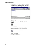
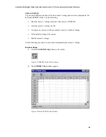
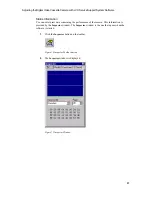
Click the Edit button on the 

EEPROM Utility

 toolbar.


 Figure 54 Edit Toolbar Button

3. 

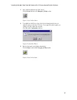
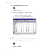
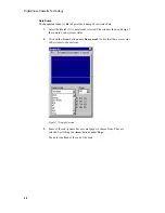
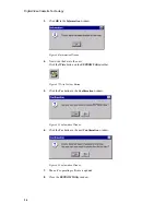
The Editing window appears. Click the 

Up

 and 

Down Arrows

 to change the

data. If you press the 

Shift

 key on the keyboard while you are clicking the

Arrows

 the data will change in steps of 10. Change the data to 00.

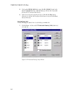
After you change the data, click the 

OK

 button.


 Figure 55 Editing Window

Restore the settings

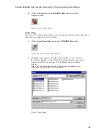
At times you may wish to restore a camera’s settings or load the camera’s default settings.

1. 

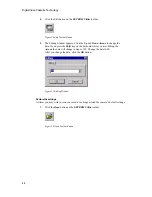
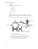
Click the 

Open

 button on the 

EEPROM Utility

 toolbar.


 Figure 56 Open Toolbar Button

Summary of Contents for GR-DVF11U

Page 1: ...VideoCassette Technology Adjusting the Digital Video Cassette Camera with JVC Service Support System Software JVC Service and Engineering Company of America Engineering Department 10 New Maple Avenue Pine Brook NJ 07058 9641 June 2001 ...

Page 2: ......

Page 3: ...DigitalVideoCassette Technology Adjusting the Digital Video Cassette Camera with JVC Service Support System Software ...

Page 4: ...served No part of this publication may be reproduced in any form nor may it be stored in a retrieval system or transmitted in any form without written permission from the Engineering Department of JVC Service and Engineering Company of America a division of JVC Americas Corp ...

Page 5: ...s Introduction 1 Required Tools 2 Software Installation 4 Camera Connection 4 Software Functions 9 Control Functions 9 Information Functions 23 Adjustment Functions 43 Data Dump Definition 92 Standard Dump 92 Deck Dump 97 ...

Page 6: ......

Page 7: ...rvice Support System software to aid technicians in camera repair All cameras now manufactured by JVC require a connection to a personal computer running JVC Service Support System software for electrical adjustments This seminar s scope is limited to the following models GR DVF11U GR DVF21U GR DVF31U GR DVM50U GR DVM70U ...

Page 8: ... YTU92001 050 Gray Scale Chart YTU94133A Infinity Adjustment Lens YTU92001B Light Box YTU93096A PC Cable QAM0099 002 Screwdriver YTU94048A Step up Ring See Table 2 Jig Cable See Table 2 Service Support Software See Table 2 Extension Connector See Table 3 AC Adapter See Table 4 Docking Station See Table 4 Filters See Table 5 Digital Voltmeter Frequency Counter 300 MHz Oscilloscope Personal Computer...

Page 9: ...R DVF11U AA V20U LYH30039 001A GR DVF21U AA V20U LYH30039 001A GR DVF31U AA V20U LYH30039 001A GR DVM50U AA V50U CU V501U LY31176 003A GR DVM70U AA V50U CU V501U LY31176 004A Table 4 Required Accessories Filter ND 0 3 ND 0 4 ND 1 2 ND 3 0 LLB12 Table 5 Required Filters Personal Computer Specifications Operating System Microsoft Windows 95 or Windows 98 Processor 160 MHz Pentium Minimum RAM Require...

Page 10: ...een prompts you to open the readme file Click the check box before you click the Finish button Read the readme file when it is displayed 5 After you have read the readme file select Exit from the File menu to close the file Camera Connection Connect the camera to the computer 1 Connect the PC Cable s P N QAM0099 002 DSUB 9 plug to a free serial communications port on the computer Make a note of wh...

Page 11: ...ing the Digital Video Cassette Camera with JVC Service Support System Software 5 GR DVF11U GR DVF21U GR DVF31U Figure 2 GR DVF11U Computer Connection GR DVM50U GR DVM70U Figure 3 GR DVM50U Computer Connection ...

Page 12: ...Service Support System software 3 Select the appropriate Serial Port in the Serial Port Configuration dialog box Click the OK button Figure 4 Serial Port Configuration 4 Select the NTSC Color System and New YTU93096A Light Box Type in the Camera Configuration dialog box Click the OK button Figure 5 Camera Configuration 5 Wait for the software to start The main program window appears Figure 6 Title...

Page 13: ...clicking the Close button that is the x button in the upper right corner of the window Figure 7 Inspector Window 7 Notice that the window contains a menu bar and a toolbar The menu bar has three menus with several entries File Inspector Controller Camera DSP Deck VTR Automatic Running Utility EEPROM Utility Emergency Utility Adjustment Utility Exit ...

Page 14: ...pears These descriptions are called ToolTips The ToolTips disappear after several seconds In addition the toolbar button description also appears in the status bar Figure 8 ToolTips The description for each of the 12 buttons on the toolbar is Inspector Camera Controller DSP Controller Deck Controller VTR Automatic Running Utility EEPROM Utility Emergency Utility Adjustment Utility Zoom Tele Zoom W...

Page 15: ...ntrol Functions The control functions are divided into two groups Camera Operation Programmed Camera Operation Camera Operation There are three windows that control camera operation Deck Controller Camera DSP Deck Controller The Deck Controller window controls the tape transport Use the following procedure to learn about the Deck Controller window 1 Click the Deck Controller toolbar button Figure ...

Page 16: ...y Fast Forward Stop and Pause buttons is the same as the buttons located on the unit itself The Eject button operates only when the cassette cover is open 6 The Deck Controller window allows you to turn off the ATF Automatic Tracking Click the Down Arrow next to ATF and select OFF 7 The Editing window opens Hold down the keyboard s Shift key and click the Up Arrow in the Editing window five times ...

Page 17: ...licking the SP Tape Speed button 11 Click the Recording Start Stop button to start recording Record for a few minutes 12 Click the Recording Start Stop button again to pause recording 13 Click the LP Tape Speed button to select the LP mode Click the Recording Start Stop to continue recording Camera Controller The Camera Controller window controls the camera Use the following procedure to learn abo...

Page 18: ...ra Controller Window 3 Experiment with the settings until you understand the effect of each one Iris AUTO Iris opens to the optimum setting CLOSE Iris is closed OPEN Iris is fully opened PWM Iris is set by the software user AGC AUTO AGC is on OFF AGC is off ON AGC gain is set to the maximum ...

Page 19: ...dow Main Program Window The zoom and focus functions are controlled from the main program window Use the following procedure to learn about them 1 Position the mouse pointer over the Zoom Wide toolbar button Click and hold the left mouse button Notice that the camera s lens moves toward the wide angle position as long as the mouse button is held down 2 Repeat the above step except use the Zoom Tel...

Page 20: ... the digital zoom function 6 Disable the automatic focus operation by clicking the Auto Focus check box Notice the Focus Far and Focus Near buttons are now operational 7 The operation of the focus buttons is similar to that of the zoom buttons Experiment with the Focus Near and Focus Far buttons DSP Controller 1 Select Controller from the File menu Then select DSP Figure 15 DSP Controller Menu 2 T...

Page 21: ...amera s mechanism by repeating mechanical operations over and over Use this function to stress the camera s mechanism and induce intermittent mechanical failures There are three demonstrations Create a List and Run it Use the following procedure to create and run a list of operations for the camera to perform 1 Click the VTR Automatic Running Utility button on the toolbar Figure 17 VTR Automatic R...

Page 22: ...window Then click the Right Arrow button Figure 19 VTR Automatic Running Utility Window 4 The Timer Setting window appears This windows sets the length of time the unit will perform an operation For example set the time for this function to ten seconds Position the mouse pointer over the Second slider Click and hold the mouse button Drag the slider to the right until the display in the status bar ...

Page 23: ... the time required to cycle through the list is one minute This is indicated where it states Total Time 00 01 00 underneath the User s Command List To the left of the time indication is the Loop Count selector Click the Up Arrow next to the Loop Count twice This sets the number of cycles to two Now click the Start button in the VTR Automatic Running Utility window Note If you set the Loop Count to...

Page 24: ...r s Command List The status bar at the bottom of the window indicates The tape position and speed for example 28 40 23 SP The current loop for example Loop 1 The time the process started for example Start 10 52 54 The elapsed time for example Progress 00 00 04 9 The process continues until the two loops are complete The Information window then appears Click the OK button Figure 23 Information Wind...

Page 25: ...st Now click the Up Arrow between the two command lists twice Notice that the play operation is moved to the top of the list 3 Double click the PLAY 00 00 10 entry in the User s Command List The Timer Setting window opens Change the timer duration to 20 seconds and click the OK button Figure 25 Timer Setting Window 4 Click on the PLAY 00 00 20 entry in the User s Command List Now click the Down Ar...

Page 26: ... from the list 6 If you were to choose to clear the list you could click the Clear button However we will use the list in the next section so do not click the Clear button at this time Open and Save a List Use the following procedure to save your list and open another list 1 Click the Save button in the VTR Automatic Running Utility window to save your list Figure 26 VTR Automatic Running Utility ...

Page 27: ... box next to File name Type in a file name such as MyList Click the Save button in the Save As window to save the list as a file The list is saved and the Save As window closes Figure 27 Save As Window 3 Click the Open button in the VTR Automatic Running Utility window to get a previously saved list Figure 28 VTR Automatic Running Utility ...

Page 28: ...Open button in the Open window The sample list is opened and the commands appear in the User s Command List in the VTR Automatic Running Utility window Figure 29 Open Window 5 Experiment with the utility When you are finished close the VTR Automatic Running Utility window Click the Yes button in the Confirmation window Figure 30 Confirmation Window ...

Page 29: ...ersion number and the Service Support System software s version number CPU Version Number Obtain the camera CPU s version number as follows 1 Select About CPU from the Option menu Figure 31 Option About CPU Menu 2 The Information window displays the camera CPU s version number Figure 32 CPU Version Window 3 Click the OK button to close the Information window ...

Page 30: ...r Obtain the software s version number as follows 1 Select About from the Help menu Figure 33 Help About Menu 2 The About window displays the software s version number Figure 34 About Service Support System Window 3 Click the OK button to close the About window ...

Page 31: ...mera experienced Use the following procedure to retrieve and store failure information 1 Click the Emergency Utility toolbar button Figure 35 Emergency Utility Toolbar Button 2 The Emergency Utility window appears Figure 36 Emergency Utility Window 3 Read the camera s failure information Click the Read button on the Emergency Utility toolbar Figure 37 Read Toolbar Button ...

Page 32: ...8 Emergency Utility Window 5 Save the failure information Click the Save button on the Emergency Utility toolbar Figure 39 Save Toolbar Button 6 The Save As window appears Click in the text box next to File name Type in a new file name Most technicians use the camera s serial number as the file name Click the Save button in the Save As window to save the failure information as a file The informati...

Page 33: ...se Toolbar Button 8 You should do this after you have saved the information and before you return the camera to the user This way if you repair the camera again you will know if a new failure has occurred Click Yes in the Confirmation window Figure 42 Confirmation Window 9 Retrieve previously saved failure information Click the Open button on the Emergency Utility toolbar Figure 43 Open Toolbar Bu...

Page 34: ...ndow The failure information is displayed in the Emergency Utility window Figure 44 Open Window 11 The Print button on the Emergency Utility toolbar prints the failure information Figure 45 Print Toolbar Button 12 The Copy button on the Emergency Utility toolbar copies the failure information to the clipboard Figure 46 Copy Toolbar Button 13 Close the Emergency Utility window ...

Page 35: ...gs contained in the camera s EEPROM Store the camera s settings to a file Compare one camera s settings to another camera s or default settings Write default settings to the camera Edit the camera s settings Use the following procedures to learn about manipulating the camera s settings Read the settings 1 Click the EEPROM Utility button on the toolbar Figure 47 EEPROM Utility Toolbar Button 2 The ...

Page 36: ...lected cell s address is 00 and its value is 20 You can also determine the cell s address by looking at the heading for its row and column For example the cell s address in the upper left corner is 000 The cell s address immediately below it is 010 Figure 50 EEPROM Utility Window Save the settings It is prudent to save the camera s settings before altering them or before adjusting the camera 1 To ...

Page 37: ...ton in the Save As window to save the settings information as a file The information is saved and the Save As window closes Figure 52 Save As Window Edit the settings On some occasions you may need to edit the camera settings manually 1 Click on the cell you wish to change In this case we will change the setting in cell 25A Click on cell 25A to select it You can find cell 25A by looking at the int...

Page 38: ...f you press the Shift key on the keyboard while you are clicking the Arrows the data will change in steps of 10 Change the data to 00 After you change the data click the OK button Figure 55 Editing Window Restore the settings At times you may wish to restore a camera s settings or load the camera s default settings 1 Click the Open button on the EEPROM Utility toolbar Figure 56 Open Toolbar Button...

Page 39: ...en window Figure 57 Open Window 3 The Open window disappears and the settings data from the file is loaded into the EEPROM Utility window 4 Load the settings information into the unit Click the Write button on the EEPROM Utility toolbar Figure 58 Write Toolbar Button 5 Click the Yes button in the Confirmation window The data from the file is now in the unit Figure 59 Confirmation Window Compare se...

Page 40: ...may find the name of the appropriate file by clicking the Help button and reading the help file that is included with the Service Support System software 3 After you have opened the default settings file the Information window appears This window displays the number of differences between your camera and the file Click the OK button in the Information window Figure 61 Information Window 4 The diff...

Page 41: ...eased in conjunction with a service bulletin 1 Click the Load Doctor Data button on the EEPROM Utility toolbar Figure 64 Load Doctor Data Toolbar Button 2 The Open window appears Click the name of the file you saved earlier in the list below Look in to select it This should be the serial number of your camera and the file extension rom Click the Open button in the Open window Note This is for demo...

Page 42: ... unit Click the Write button on the EEPROM Utility toolbar Figure 67 Write Toolbar Button 5 Click the Yes button in the Confirmation window Figure 68 Confirmation Window 6 Click the Yes button in the next Confirmation window Figure 69 Confirmation Window 7 The unit s operating software is updated 8 Close the EEPROM Utility window ...

Page 43: ...ain raw data concerning the performance of the camera This information is provided by the Inspector window The Inspector window is the one that opens when the software is started 1 Click the Inspector button on the toolbar Figure 70 Inspector Toolbar Button 2 The Inspector window is displayed Figure 71 Inspector Window ...

Page 44: ...selected The window shows a dump of the camera s sub systems status 2 Click on the Arrow button under Dump mode Notice that there are several sub systems to choose from Figure 72 Dump Selection 3 Some of the sub systems have several pages to choose from They are selected by clicking the Arrow buttons under Page The data is defined at the end of the book ...

Page 45: ...displays a graphic of the camera s image Don t expect too much detail the image is divided into a 8 x 6 image You can select either the luminance or each of the colors in the image Figure 73 Camera Image 2 Underneath the graphic the Inspector window displays the same image information except it is in a numeric format rather than a graphic format ...

Page 46: ...ette Play back the tape 3 Click Error Rate tab in the Inspector window 4 The Error Rate window appears Figure 74 Error Rate Window 5 This window displays the number of errors that occur during playback of a tape 6 Observe the readings Notice that the data constantly changes The error rate is an average of the Error Count over a short period of time 7 The Viterbi circuit can be switched off or on u...

Page 47: ...annel 1 head CH2 Outer Error 1V Audio Percentage of audio block errors per frame for the channel 2 head CH2 Outer Error 1V Video Percentage of video block errors per frame for the channel 2 head CH1 Sync Count 1V Percentage of errorless sync blocks per frame for the channel 1 head CH2 Sync Count 1V Percentage of errorless sync blocks per frame for the channel 2 head Error Count CH1 Error count for...

Page 48: ...cates the focus position during the zooming operation The white line on the left indicates the focus far position The white line on the right indicates the focus near position The magenta line indicates the focus setting of the camera The top on the display indicates the telephoto zoom position The bottom of the display indicates the wide angle zoom position 5 Click the Auto Focus check box to dis...

Page 49: ...ck Setting You can set the camera s clock to the computer s time as follows 1 Select Set Clock from the Option menu Figure 76 Option Set Clock Menu 2 Click Yes in the Confirmation window Figure 77 Confirmation Window 3 You have now set the camera s clock 4 Click OK in the Information window Figure 78 Information Window ...

Page 50: ... camera The adjustments are divided into three sections Deck Camera Optical Use the following procedure to learn about the adjustment utility 1 Click the Adjustment Utility button on the toolbar Figure 79 Adjustment Utility Toolbar Button 2 The Adjustment Utility window appears Figure 80 Adjustment Utility Window ...

Page 51: ... Camera Optical 4 Click the Down Arrow underneath the tabs to display a drop down box listing the adjustment procedures 5 The Adjustment window contains a toolbar with the following Start button Starts the adjustment Terminate button Terminates the adjustment Page 1 1 Step number and total number of steps Font Large button Increases the font size Font Small button Decreases the font size ...

Page 52: ...describes the JVC Infinity Adjustment Lens setup 1 Install the Focus Block on the end of the JVC Infinity Adjustment Lens Figure 81 Installing the Focus Chart 2 Install the Focus Chart into the threaded end of the Focus Block 3 Attach the Adapter Ring to the filter threads of the camera lens Be careful it is easy to cross thread the Adapter Ring when attaching it to the unit 4 Then attach the Infi...

Page 53: ...the Optical tab in the Adjustment Utility window 2 Select the Zoom Sensor procedure in the list box if it is not already selected Figure 82 Zoom Sensor Adjustment 3 Read the procedure 4 Click the Start button The Confirmation window appears Figure 83 Confirmation Window 5 Click the Yes button in the Confirmation window ...

Page 54: ...Focusing window 8 The Information window appears Figure 85 Information Window 9 Click OK in the Information window 10 The Best Focusing window appears Click OK in the Best Focusing window when the adjustment is complete 11 The Information window appears Figure 86 Information Window 12 Click the OK button in the Information window The Zoom Sensor adjustment is complete ...

Page 55: ...ity Sensor Adjustment 2 Read the procedure 3 Click the Start button in the Adjustment Utility window The Confirmation window appears 4 Click the Yes button in the Confirmation window 5 The Best Focusing window appears When the adjustment is complete click the OK button in the Best Focusing window 6 The Information windows appears Click the OK button in the Information window The Infinity Sensor ad...

Page 56: ... the procedure 3 Click the Start button in the Adjustment Utility window The Confirmation window appears 4 Click the Yes button in the Confirmation window 5 The Best Focusing window appears When the adjustment is complete click the OK button in the Best Focusing window 6 The Information windows appears Click the OK button in the Information window The FC Correction adjustment is complete ...

Page 57: ...nearity Adjustment 2 Read the procedure 3 Click the Start button in the Adjustment Utility window The Confirmation window appears 4 Click the Yes button in the Confirmation window 5 The Best Focusing window appears When the adjustment is complete click the OK button in the Best Focusing window 6 The Information windows appears Click the OK button in the Information window This completes the Optica...

Page 58: ...Technology 52 Camera Processing The camera processing section contains ten adjustments IR Sensor Hall Gain Offset High Light Cyan Y Gain AGC AE Hall Curve AF Filter Color Separation White Balance Difference Color Gain Matrix ...

Page 59: ...lowing procedure describes the JVC Light Box and Infinity Adjustment Lens setup 1 Remove the JVC Infinity Adjustment Lens from the unit It is best to leave the Adapter Ring on the camera lens 2 Remove the Focus Block from the end of the JVC Infinity Adjustment Lens Figure 90 Remove the Focus Chart 3 Attach a Camera Stand to the tripod mount on the bottom of the unit Focus Block with Focus Chart JV...

Page 60: ...wing the open end onto the threaded section of the Rotary Ring 8 Attach the other end of the JVC Infinity Adjustment Lens to the Adapter Ring that is still mounted on the filter threads of the camera lens 9 Load a chart into the chart holder Insert the Chart Holder into the Chart Slot of the Light Box 10 Connect a 12 0 0 2 VDC regulated power supply to the Light Box 11 Turn on the power switch whi...

Page 61: ...at the image of the chart is straight and centered on the screen If necessary use the adjustable feet on the camera stand Some adjustments require output signal of the camcorder be viewed on an oscilloscope or vectorscope Connect the video output of the camcorder to an oscilloscope and a vectorscope The video output must be terminated with a 75Ω load ...

Page 62: ... window 2 Select the IR Sensor procedure in the list box if it is not already selected Figure 92 IR Sensor Adjustment 3 Read the procedure 4 Cover the IR Sensor 5 Click the Start button The Confirmation window appears Figure 93 Confirmation Window 6 Click the Yes button in the Confirmation window ...

Page 63: ...te Camera with JVC Service Support System Software 57 7 When the adjustment is complete the Information window appears Figure 94 Information Window 8 Click the OK button in the Information window This completes the IR Sensor adjustment ...

Page 64: ...igure 95 Hall Gain Offset Adjustment 2 Read the procedure 3 Click the Start button in the Adjustment Utility window The Confirmation window appears 4 Click Yes in the Confirmation window 5 When the adjustment is complete the Information window appears 6 Click the OK button in the Information window This completes the Hall Gain Offset adjustment ...

Page 65: ...stment 2 Read the procedure 3 Remove the Chart Holder from the Light Box so the camcorder is shooting the ground glass in the Light Box 4 Click the Start button in the Adjustment Utility window The Confirmation window appears 5 Click the Yes button in the Confirmation window 6 When the adjustment is complete the Information window appears 7 Click the OK button in the Information window This comple...

Page 66: ... 97 Y Gain Adjustment 2 Read the procedure 3 Remove the Chart Holder from the Light Box so the camcorder is shooting the ground glass in the Light Box 4 Click the Start button in the Adjustment Utility window The Confirmation window appears 5 Click the Yes button in the Confirmation window The Editing window appears Figure 98 Editing Window ...

Page 67: ... Click the Up and Down Arrows in the Editing window to set the amplitude of the video output signal from the blanking level to the peak to 0 70 0 01 V p p Figure 99 Y Gain Amplitude 7 Then click the OK button in the Editing window The Information window appears 8 Click the OK button in the Information window This completes the Y Gain adjustment ...

Page 68: ...eve the desired value For example add a ND 3 0 and ND 0 3 filter for the value ND 3 3 5 Click the Start button in the Adjustment Utility window The Confirmation window appears 6 Click the Yes button in the Confirmation window The Editing window appears 7 Use an oscilloscope to observe the video output signal Click the Up and Down Arrows in the Editing window to set the amplitude of the video outpu...

Page 69: ... Digital Video Cassette Camera with JVC Service Support System Software 63 9 Click the OK button in the Information window 10 Remove the filter from the filter slot of the Light Box This completes the AGC adjustment ...

Page 70: ...ooting the ground glass in the Light Box 4 Insert a ND 0 3 Neutral Density filter into the filter slot of the Light Box 5 Click the Start button in the Adjustment Utility window The Confirmation window appears 6 Click the Yes button in the Confirmation window 7 When the adjustment is complete the Information window appears 8 Click the OK button in the Information window 9 Remove the filter from th...

Page 71: ...ter slot of the Light Box 5 Click the Start button in the Adjustment Utility window The Confirmation window appears 6 Click the Yes button in the Confirmation window 7 After the adjustment has run another Confirmation window appears Figure 104 Confirmation Window 8 Remove the ND 1 2 Neutral Density filter from the filter slot of the Light Box Then click the OK button in the Confirmation window 9 W...

Page 72: ...ure 3 Remove the Chart Holder from the Light Box so the camcorder is shooting the ground glass in the Light Box 4 Click the Start button in the Adjustment Utility window The Confirmation window appears 5 Click the Yes button in the Confirmation window 6 When the adjustment is complete the Information window appears 7 Click the OK button in the Information window This completes the Color Separation...

Page 73: ...x 4 Click the Start button in the Adjustment Utility window The Confirmation window appears 5 Click the Yes button in the Confirmation window 6 After the adjustment has run the Information window appears Figure 107 Information Window 7 Insert a LBB12 filter into the Filter Slot of the Light Box 8 Click the OK button in the Information window 9 When the adjustment is complete another Information wi...

Page 74: ...justment 2 Read the procedure 3 Insert the Chart Holder into the Chart Slot of the Light Box so the camcorder is shooting the Color Bar Chart 4 Click the Start button in the Adjustment Utility window The Confirmation window appears 5 Click the Yes button in the Confirmation window The Editing window appears Figure 109 Editing Window 6 If it not already selected click the Iris PWM tab in the Editin...

Page 75: ...0h in this example by clicking it View the video output signal using a vectorscope Click the Up and Down Arrows to alter the vector waveform Notice that the waveform varies along the y axis of the vector display 10 Select the next tab labeled 111h in this example by clicking it Click the Up and Down Arrows in the Editing window Notice that the waveform varies along the x axis of the vector display...

Page 76: ...pears 16 Read the procedure for step 2 of the adjustment 17 Insert a LBB12 filter into the Filter Slot of the Light Box 18 Click the Start button in the Adjustment Utility window to start step 2 of the adjustment The Confirmation window appears 19 Click the Yes button in the Confirmation window The Editing window appears 20 If it not already selected click the Iris PWM tab in the Editing window to...

Page 77: ... the unit so the waveform observed on the vectorscope matches the figure below Figure 112 Difference Color Gain Matrix Adjustment 2 23 Click the OK button in the Editing window 24 Click the OK button in the Information window when it appears 25 Remove the filter from the filter slot of the Light Box This completes the Camera Processing Adjustments ...

Page 78: ... VCO Center Frequency ME SP VCO Center Frequency ME LP Preparation Some adjustments require the output signal of the unit be viewed on an oscilloscope Leave the connection to the output signal as is Some adjustments require a connection to test points in the unit A Jig Connector is required to measure these test points The preparation varies according to model Refer the appropriate section ...

Page 79: ... P N YTU93082C to CN105 on the circuit board The Jig Connector has two sets of test points Use the set on the board marked with the number 14 on it The pin numbers specified in the adjustment procedures are for connector CN105 not for the Jig Connector YTU93082C Use the table to determine the Jig Connector pin number Mnemonic CN105 Pin Number Jig Connector Pin Number Main VCO 19 7 FS PLL 3 4 REC M...

Page 80: ...R DVM50U Adjustment Preparation Adjustment preparation 1 Mount the unit on its Docking Station 2 Remove the screw 3 Remove the Jig Cover 4 Attach two Extension Connectors P N YTU94145A to the Jig Connector P N YTU93091B Then connect them to CN1010 on the board YTU94145A ...

Page 81: ...lity window 2 Select the 81MHz VCO Center Frequency procedure in the list box if it is not already selected Figure 115 81MHz VCO Center Frequency 3 Read the procedure 4 Click the FA Camera tab in the Deck Controller window to put the unit in the Camera mode Figure 116 Deck Controller Window 5 Connect a digital voltmeter to the Main VCO test point on the Jig Connector ...

Page 82: ... The Editing window appears Figure 118 Editing Window 8 Monitor the amplitude of the signal Click the Up and Down Arrows in the Editing window to set the amplitude of the signal to 1 2 0 2 V DC 9 Then click the OK button in the Editing window The Information window appears Figure 119 Information Window 10 Click the OK button in the Information window This completes the 81MHz VCO Center Frequency a...

Page 83: ...k Controller window to put the unit in the Deck mode 4 Load the Alignment Tape MC 1 into the unit 5 Use the Deck Controller window to Play the Color Bar section of the tape 6 Click the Start button in the Adjustment Utility window The Confirmation window appears 7 Click the Yes button in the Confirmation window 8 When the adjustment is complete the Information window appears 9 Click the OK button ...

Page 84: ...P Controller to turn on the Color Bars 5 Click the Start button in the Adjustment Utility window The Confirmation window appears 6 Click the Yes button in the Confirmation window The Editing window appears 7 Use an oscilloscope to observe the video output signal Click the Up and Down Arrows in the Editing window to set the amplitude of the Sync Pulse of the video output signal to 0 28 0 02 V p p o...

Page 85: ... Cassette Camera with JVC Service Support System Software 79 8 Then click the OK button in the Editing window The Information window appears 9 Click the OK button in the Information window This completes the Sync Level adjustment ...

Page 86: ...ode 4 Use the DSP Controller to turn on the Color Bars 5 Click the Start button in the Adjustment Utility window The Confirmation window appears 6 Click the Yes button in the Confirmation window The Editing window appears 7 Use an oscilloscope to observe the video output signal Click the Up and Down Arrows in the Editing window to set the amplitude of the Color Burst of the video output signal to ...

Page 87: ...Cassette Camera with JVC Service Support System Software 81 8 Then click the OK button in the Editing window The Information window appears 9 Click the OK button in the Information window This completes the Burst Level adjustment ...

Page 88: ... counter to the FS PLL test point on the Jig Connector 6 Click the Start button in the Adjustment Utility window The Confirmation window appears 7 Click the Yes button in the Confirmation window The Editing window appears Figure 126 Editing Window 8 If it not already selected click the First tab in the Editing window to select it 9 Use a frequency counter to observe the oscillator frequency 10 Cli...

Page 89: ... the Editing window to set the frequency to 11 2896 MHz 110 kHz 13 Click the Third tab in the Editing window to select it 14 Click the Up and Down Arrows in the Editing window to set the frequency to 8 192 MHz 80 kHz 15 Then click the OK button in the Editing window The Information window appears 16 Click the OK button in the Information window This completes the Fs PLL adjustment ...

Page 90: ...nnel 1 input of an oscilloscope to the REC MON test point on the Jig Connector 5 Connect the channel 2 input of an oscilloscope to the HID test point on the Jig Connector Use this signal to trigger the oscilloscope 6 Load a new tape into the unit 7 Use the Deck Controller window to start recording at the SP Tape Speed 8 Click the Start button in the Adjustment Utility window The Confirmation windo...

Page 91: ...e amplitude of the signal to 420 5 mV p p or the value specified in the software Figure 128 Set the Head Record Current 11 Hold the Shift key down and click the Up Arrow in the Editing window This changes the data by 10h 12 Click the Recording Log check box in the Deck Controller window to activate the recording log 13 Again hold the Shift key down and click the Up Arrow in the Editing window ...

Page 92: ...cording for about 30 seconds 17 Hold down the Shift key and click the Down Arrow in the Editing window Notice the data changes by 10h Also notice that another entry is added to the Recording Log Continue recording for about 30 seconds 18 Again hold down the Shift key and click the Down Arrow in the Editing window Continue recording for about 30 seconds 19 Repeat the above step two times There shou...

Page 93: ... Confirmation window The Editing window appears 33 Click on the Arrow buttons in the Editing window to set its value to the one that has the lowest Error Rate 34 Then click the OK button in the Editing window The Information window appears 35 Click the OK button in the Information window The Error Rate for each head should be below 498 If the error rate exceeds the maximum allowable values the hea...

Page 94: ...for three or four minutes 5 Click the FA Deck tab in the Deck Controller window to put the unit in the Deck mode 6 Use the Deck Controller window to rewind the tape to the beginning of your recording Then play your recording 7 Click the Start button in the Adjustment Utility window The Confirmation window appears 8 Click the Yes button in the Confirmation window The adjustment starts The first par...

Page 95: ... 12 Click the OK button in the Information window The Error Rate for each head should be below 498 If the error rate exceeds the maximum allowable values the head and tape transport system should be cleaned If the error rate still exceeds the maximum allowable values you should consider that the head may have failed or the preamp shield is loose Best results are obtained when the camera is fully a...

Page 96: ...n play your recording 7 Click the Start button in the Adjustment Utility window The Confirmation window appears 8 Click the Yes button in the Confirmation window The adjustment starts The first part of the adjustment is performed automatically View the status bar on the bottom of the Adjustment Utility window to monitor the adjustment progress 9 After completion of the automatic portion of the adj...

Page 97: ...e obtained when the camera is fully assembled prior to starting the adjustment Strong radiation in close proximity to the camera such as a computer or video monitor will affect the error rate reading Usually giving a false higher error rate This completes the VCO Center Frequency ME Tape LP Speed adjustment Conclusion This completes the adjustments 1 Select Exit from the File menu in the Service S...

Page 98: ...peration BPF H Voltage Low Order Byte 12 Focus Operation BPF H Voltage High Order Byte 13 Focus Control See Table 11 14 Iris Control See Table 12 15 White Balance Control See Table 13 16 Camera Shake Detection See Table 14 17 AGC Level Regulation 18 Focus Sensor Voltage 19 Zoom Sensor Voltage 20 Focusing Operation See Table 15 21 AE Operation See Table 16 22 White Balance Operation See Table 17 23...

Page 99: ...us Mode Auto Focus Manual Focus Table 11 Data Dump Focus Control Iris Control Bit Description High Low 7 Shutter Control Manual Auto 6 Sport Mode Control On Off 5 Portrait Mode Control On Off 4 Manual Shutter Control On Off 3 Iris Control Manual Auto 2 User Iris Control Manual Auto 1 AGC Control AGC Manual AGC Auto 0 Manual AGC Control AGC On AGC Off Table 12 Data Dump Iris Control White Balance C...

Page 100: ...5 Data Dump Focus Operation AE Operation Bit Description High Low 4 Slow Shutter Operation Yes No 3 Video Flicker Yes No 2 Peak Area Switching Iris Closing Flag Closed 0 Iris Opening Flag Open Not Opened Table 16 Data Dump AE Operation White Balance Operation Bit No Control In Detail High Low 0 WB Open Control Data Yes No Table 17 Data Dump White Balance Operation Shutter Speed Data Shutter Speed ...

Page 101: ... Table 19 Data Dump Standard Mode Page 1 CPU Initialization Bit No Control In Detail High Low 3 Iris Initialization End Flag Initialization Complete Initializing 2 EIS Initialization End Flag Initialization Complete Initializing 1 WB Initialization End Flag Initialization Complete Initializing 0 AF Initialization End Flag Initialization Complete Initializing Table 20 Data Dump CPU Initialization F...

Page 102: ...ne Pack Found Not Found Table 22 Data Dump Special Effects Setting Low Byte Special Effects Setting High Byte Bit Description High Low Notes 6 TG Phase Data Request Request No Internal Control 5 PS Mode Control PS Normal 4 Blue Back Control On Off 3 Memory Zoom Control SW On Off Key Information 2 Snapshot Picture Memory Active Not Active 1 Picture Memory Active Not Active 0 No Slow Shutter Yes No ...

Page 103: ...ta 4 See Table 30 10 11 12 13 Total Time Code Data Frames 14 Total Time Code Data Seconds 15 Total Time Code Data Minutes 16 Total Time Code Data Hours 17 Switch Data 1 See Table 31 18 Switch Data 2 See Table 32 19 Strobe Information See Table 33 20 21 Fading Photographing Data See Table 34 22 23 24 25 26 Error Data See Table 35 27 Previous Error Data See Table 35 28 Other Information 1 See Table3...

Page 104: ...er Recording ADUB 0X0C After Record Pause ADBP 0X0D Retake Forward RFF 0X0E Retake Reverse RREW 0X0F Change Speed Play VPLY 0X10 Unloading Rehearsal RHUL 0X11 Eject Rehearsal RHEJ 0X12 Loading Rehearsal RHLD 0X13 Record REC 0X14 Record Pause RECP 0X15 DV Record DVRC 0X16 DV Record Pause DVRP 0X17 Insert INS 0X18 Insert Pause INSP 0X19 Soft Stop SFTP Table 25 Data Dump VTR Mode Mechanism Position D...

Page 105: ...eaning Tape Cleaning Tape Cleaning Tape 4 In Recording Recording from next Frame Recording to the 2nd Frame 3 0 Point In Detection Normal 2 1394 Cable Detected Not Detected 1 Tape Detected Not Detected 0 1394 Signal Detected Not Detected Table 28 Data Dump Sensor 2 Sensor 3 Bit Description High Low 7 AGCMS Copy Inhibit Not Detected 2 Emergency Mode Off On 1 PB Encoding Mode 11 32 kHz 12 Bit 00 48 ...

Page 106: ...ed Not Finished 0 Charge Charging Not Charging Table 33 Data Dump Strobe Information Fading Information Bit Description High Low 1 Photograph Executing Not Executing 0 Fader Executing Not Executing Table 34 Data Dump Fading Information Error Information 1 Bit Description High Low 7 Tape Emergency Detected Not Detected 6 Camera Emergency Detected Not Detected 5 Capstan Error Detected Not Detected 4...

Page 107: ...d Yes No 2 Write Enable Tape Yes No 1 Voltage Attenuation Yes No 0 Rehearsal Yes No Table 36 Data Dump Other Information 1 Other Information 2 Bit Description High Low 7 Tape End Yes No 6 Tape Start Yes No 5 Tape Loaded Yes No 4 Ltl Detection Detected Not Detected 3 Emergency Yes Occur No 2 Dew Yes Occur No 1 Housing Closed Open 0 Interval Yes No Table 37 Data Dump Other Information 2 System Mode ...

Page 108: ...oller Window in FA Camera Mode 11 Figure 13 Camera Controller Menu 11 Figure 14 Camera Controller Window 12 Figure 15 DSP Controller Menu 14 Figure 16 DSP Controller Window 14 Figure 17 VTR Automatic Running Utility Toolbar Button 15 Figure 18 Deck Mode Confirmation Window 15 Figure 19 VTR Automatic Running Utility Window 16 Figure 20 Timer Setting Window 16 Figure 21 Running Utility Stopped 17 Fi...

Page 109: ... Button 25 Figure 38 Emergency Utility Window 26 Figure 39 Save Toolbar Button 26 Figure 40 Save As Window 26 Figure 41 Erase Toolbar Button 27 Figure 42 Confirmation Window 27 Figure 43 Open Toolbar Button 27 Figure 44 Open Window 28 Figure 45 Print Toolbar Button 28 Figure 46 Copy Toolbar Button 28 Figure 47 EEPROM Utility Toolbar Button 29 Figure 48 Main EEPROM Utility Window 29 Figure 49 Read ...
Page 110: ... Figure 68 Confirmation Window 36 Figure 69 Confirmation Window 36 Figure 70 Inspector Toolbar Button 37 Figure 71 Inspector Window 37 Figure 72 Dump Selection 38 Figure 73 Camera Image 39 Figure 74 Error Rate Window 40 Figure 75 Z Track Window 42 Figure 76 Option Set Clock Menu 43 Figure 77 Confirmation Window 43 Figure 78 Information Window 43 Figure 79 Adjustment Utility Toolbar Button 44 Figur...

Page 111: ...e 97 Y Gain Adjustment 60 Figure 98 Editing Window 60 Figure 99 Y Gain Amplitude 61 Figure 100 AGC Adjustment 62 Figure 101 AGC Amplitude 62 Figure 102 AE Hall Curve Adjustment 64 Figure 103 AF Filter 65 Figure 104 Confirmation Window 65 Figure 105 Color Separation Adjustment 66 Figure 106 White Balance Adjustment 67 Figure 107 Information Window 67 Figure 108 Difference Color Gain Matrix Adjustme...

Page 112: ...stment 78 Figure 122 Set the Sync Level 78 Figure 123 Burst Level Adjustment 80 Figure 124 Set the Burst Level 80 Figure 125 Fs PLL Adjustment 82 Figure 126 Editing Window 82 Figure 127 Head Record Current Adjustment 84 Figure 128 Set the Head Record Current 85 Figure 129 Deck Controller Window 86 Figure 130 VCO Center Frequency ME Tape SP Speed 88 Figure 131 Adjustment Utility Window Status Bar 8...

Page 113: ...ocus Control 93 Table 12 Data Dump Iris Control 93 Table 13 Data Dump White Balance 93 Table 14 Data Dump Camera Shake Detection 93 Table 15 Data Dump Focus Operation 94 Table 16 Data Dump AE Operation 94 Table 17 Data Dump White Balance Operation 94 Table 18 Data Dump Shutter Speed 94 Table 19 Data Dump Standard Mode Page 1 95 Table 20 Data Dump CPU Initialization 95 Table 21 Data Dump Focus Erro...

Page 114: ...e 31 Data Dump Switch 1 100 Table 32 Data Dump Switch 2 100 Table 33 Data Dump Strobe Information 100 Table 34 Data Dump Fading Information 100 Table 35 Data Dump Error Information 100 Table 36 Data Dump Other Information 1 101 Table 37 Data Dump Other Information 2 101 Table 38 Data Dump System Mode 101 ...

Page 115: ......

Reviews: