background image

26

 EN

VIDEO   RECORDING

  Advanced Features

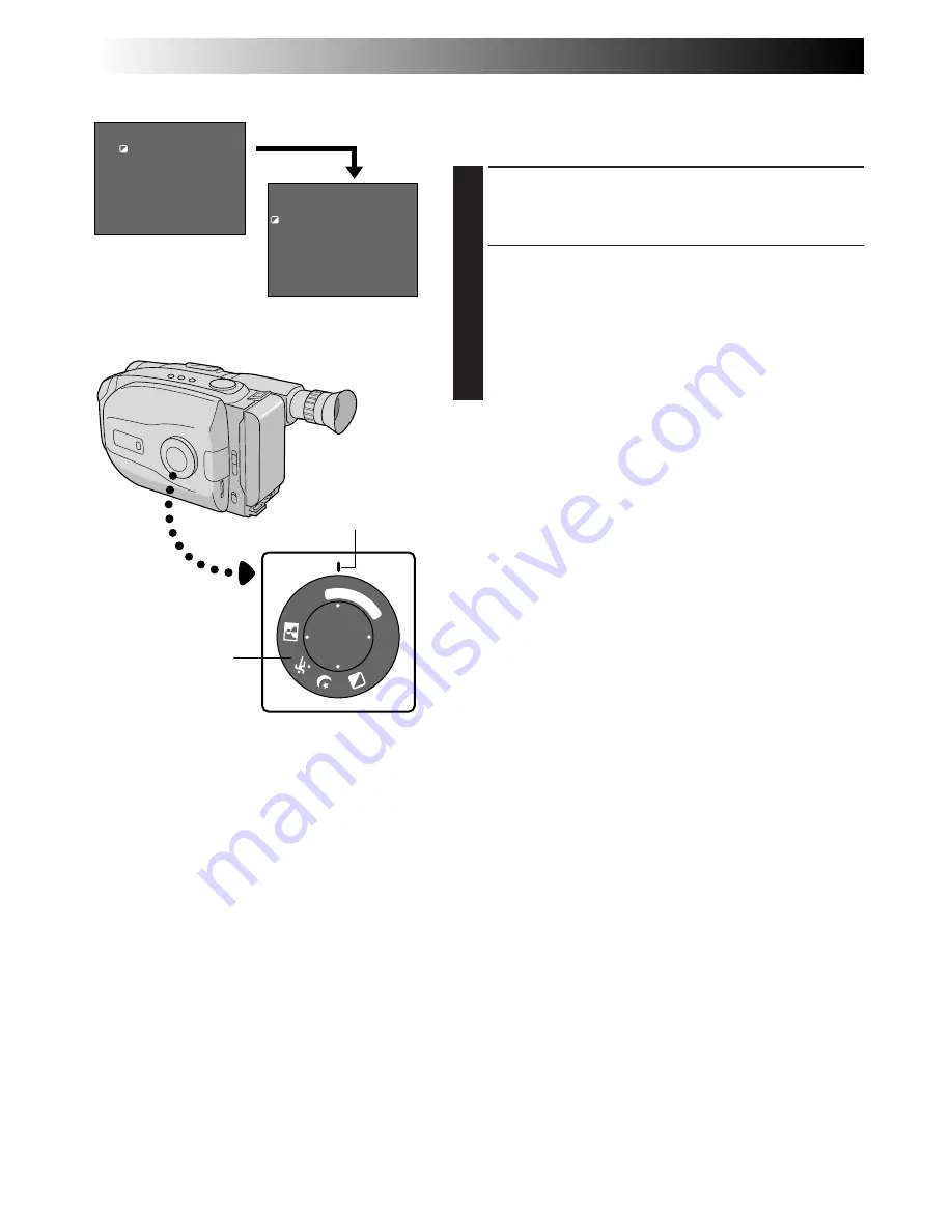
Program AE With Special Effects

All you have to do to access any of the variety of
shooting effects is to turn the Select Dial.

SELECT MODE

1

Turn the Select Dial until the symbol of the function
you want is aligned with the mark.

•The selected mode’s name and its indication are

displayed for approx. 1 second. Then the name
disappears, and only the indication remains. The
mode is activated.

•When Auto Mode Lock or Auto Mode Release

mode is selected, only the mode’s name is
displayed. Then the name disappears and the
mode is activated.

NOTES:

Only one effect can be engaged at a time.

The screen becomes slightly reddish when the Fade/
Wipe (

Z

 pg. 28) is used in the Sepia mode.

The screen becomes slightly dark in the High Speed
Shutter mode. Use in well-lit situations.

In the High Speed Shutter or Sports modes, picture
color may be adversely affected if subject is lit by
alternating discharge-type light sources such as
flourescent or mercury-vapor lights.

SEPIA

1/

20

00

F

G

N

D

AUTO M

OD

E

LOCK

REL

EA

SE

WIDE

TITLE

EFFECT

SUPER

LOLUX

After 1 sec.

1 second later, the mode is activated.

Viewfinder

Mark

Select Dial

Summary of Contents for GR-AX999UM

Page 1: ...GR AX999UM COMPACT VHS CAMCORDER INSTRUCTIONS LYT0108 001A ENGLISH EN Compact VHS ...

Page 2: ...emble heat above 100 C or incinerate Replace battery with Maxell Panasonic Matsushita Electric Sanyo or Sony CR2025 use of another battery may present a risk of fire or explosion n Dispose of used battery promptly n Keep away from children n Do not disassemble and do not dispose of in fire SAFETY PRECAUTIONS WARNING TO PREVENT FIRE OR SHOCK HAZARD DO NOT EXPOSE THIS UNIT TO RAIN OR MOISTURE CAUTIO...

Page 3: ...ns But improper use can result in potential electrical shock or fire hazards This product has been engineered and manufactured to assure your personal safety In order not to defeat the built in safeguards observe the following basic rules for its installation use and servicing ATTENTION Follow and obey all warnings and instructions marked on your product and its operating instruc tions For your sa...

Page 4: ...ding amplifiers that produce heat SERVICING 1 Servicing If your product is not operating correctly or exhibits a marked change in performance and you are unable to restore normal operation by following the detailed procedure in its operating instructions do not attempt to service it yourself as opening or removing covers may expose you to dangerous voltage or other hazards Refer all servicing to q...

Page 5: ... Z pg 20 Picture Stabilizer Z pg 21 Integrated Auto Light Z pg 23 Zoom in Zoom out Digital Still Camera Built in PC communication capable Z pg 46 61 Program Manager II Z pg 26 39 Program AE with Special Effects Fade Wipe Wide Super LoLux Instant Title Menu Adjustment Focus Exposure Control and so on Cassettes marked can be used with this camcorder The Logical Choice The only compact video cassette...

Page 6: ...HS VCR using the Cassette Adapter VHS Playpak Z pg 43 1 Slide the LENS COVER Open Close Switch to open the lens cover 2 Set the System Select Switch to VIDEO 3 Set the Power Switch to CAMERA The power indicator will light and an image will appear 4 Press the Recording Start Stop Button Recording starts To stop recording temporarily momentarily press the Recording Start Stop Button once again For m...

Page 7: ...tton to select the still image you want to view For more details Z pg 53 1 Slide the LENS COVER Open Close Switch to open the lens cover 2 Set the System Select Switch to D S C 3 Set the Power Switch to CAMERA The power indicator will light and an image will appear 4 Press the SNAPSHOT Button A still image is shot and is stored in the camcorder s memory For more details Z pg 46 SUPPLY POWER PLAYBA...

Page 8: ...asic Recording 18 Basic Features 20 Advanced Features 26 VIDEO PLAYBACK 40 Basic Playback 40 Features 41 Using The Cassette Adapter 43 BASIC CONNECTIONS TO VCR 44 TAPE DUBBING 45 DIGITAL STILL CAMERA D S C SHOOTING 46 Basic Shooting 46 Advanced Features 48 D S C PLAYBACK 53 Basic Playback 53 Advanced Features 54 Connection 61 USING REMOTE CONTROL UNIT 62 Random Assemble Editing 64 Insert Editing V...

Page 9: ...FICATIONS 84 OPTIONAL ACCESSORIES 84 PROVIDED ACCESSORIES AC Power Adapter Charger AA V15U Cassette Adapter VHS Playpak C P7U Battery Pack BN V18U Remote Control Unit RM V705U CD ROM including two software programs DC Cord Shoulder Strap Lithium Battery CR2025 x 2 for clock operation and remote control unit PC Connection Cable x 2 for Macintosh for Windows PC ...

Page 10: ...TTERY PACK 2 Slide BATT RELEASE and pull out the battery pack ATTENTION Before detaching the power source make sure that the camcorder s power is turned off Failure to do so can result in a camcorder malfunction REFRESH The AC power adapter features a REFRESH function that allows you to fully discharge the battery pack before recharging Perform the REFRESH function after no less than 5 chargings T...

Page 11: ...n t allow it to discharge in container such as a bag If you stop recharging or discharging part way through make sure to remove the battery pack before unplugging the adapter s AC cord Remove the battery pack from the adapter immediately after discharging To avoid interference with reception do not use the AC Power Adapter Charger near a radio Make sure you unplug the DC cord before charging or di...

Page 12: ...ck battery compartment cover while pressing the release tab REMOVE BATTERY when replacing 3 Insert a pointed non metallic object between the battery and the compartment A and pull the battery out INSERT BATTERY 4 Ensure that the plus side is up and insert a CR2025 lithium battery and push it in CLOSE COVER 5 Close the compartment cover until it clicks in place NOTE See SAFETY PRECAUTIONS Z pg 2 fo...

Page 13: ...nd then press it When the hour setting begins blinking rotate the MENU Jog Dial until the correct setting appears and then press it When the hour setting stops blinking and the minute setting begins blinking rotate the MENU Jog Dial until the correct setting appears and then press it The minute setting stops blinking START CLOCK OPERATION 5 When none of these settings YEAR MONTH DAY TIME blinks ro...

Page 14: ... Recording Start Stop Button and Power Zoom Button Refasten the Velcro strip Viewfinder Adjustment POSITION VIEWFINDER 1 Adjust the viewfinder manually for best viewability see illustration at left SELECT MODE 2 Set the Power Switch to CAMERA ADJUST DIOPTER 3 Turn the Diopter Adjustment Control until the indications in the viewfinder are clearly focused Recording Start Stop Button Power Zoom Butto...

Page 15: ...yelet 3 making sure the strap isn t twisted ADJUST LENGTH 2 Adjust as shown in the illustration at left 1 CAUTION When using a tripod be sure to open and extend its legs fully to stabilize the camcorder To prevent damage to the unit caused by falling over do not use a small sized tripod Tripod Mounting ALIGN AND TIGHTEN 1 Align the screw and camera direction stud on the tripod with the camera s mo...

Page 16: ...ERA Turn the Select Dial to any position except AUTO LOCK then press the MENU Jog Dial SELECT FUNCTION 2 Rotate the MENU Jog Dial to move the highlight bar to TAPE LENGTH then press it The TAPE LENGTH Setting Menu appears SET TAPE LENGTH 3 Rotate the MENU Jog Dial to move the highlight bar to the correct setting T20 20 minutes of recording time T30 30 minutes and T40 40 minutes in SP If you decide...

Page 17: ...ess a power supply is attached Make sure that the tape is not slack when loading the cassette If there is any slack turn the gear on the cassette in the direction of the arrow to take up the slack Make sure the Erase Protection tab is in the position that allows recording If not slide the tab Some cassettes have removable tabs If the tab has been removed cover the hole with adhesive tape The casse...

Page 18: ... RECORD STANDBY MODE 2 Slide the LENS COVER Open Close Switch to open the lens cover Set the System Select Switch to VIDEO then set the Power Switch to CAMERA The power indicator lights and the camcorder enters the Record Standby mode The scene you re aimed at appears on the viewfinder screen with the word PAUSE superimposed upon it START SHOOTING 3 Press the Recording Start Stop Button REC appear...

Page 19: ...D also appears when a cassette whose tape is already at its end is loaded If the Record Standby mode continues for 5 minutes without performing Zoom or any other operations the camcorder s power shuts off automatically Set the Power Switch to POWER OFF and then back to CAMERA to turn the camcorder on again If the Recording Start Stop Button is pressed after the Record Standby mode has continued fo...

Page 20: ...n press it The ZOOM SPEED Setting Menu appears 3 Rotate the MENU Jog Dial to move the highlight bar to the desired speed and press it twice The Menu Screen disappears and setting is completed NOTES Focusing may become unstable during Zooming In this case set the zoom while in Record Standby lock the focus by using the manual focus Z pg 35 then zoom in or out in Record mode The zoom level indicator...

Page 21: ... Stop Button to start recording NOTE Noise may appear during Retake This is normal FEATURE Picture Stabilizer PURPOSE To compensate for unstable images caused by camera shake particularly at high magnification OPERATION 1 Press P STABILIZER appears n To switch off the Picture Stabilizer press P STABILIZER The indicator disappears NOTES Accurate stabilization may not be possible if hand shake is ex...

Page 22: ...rmed the Date Time Setting procedure Z pg 13 If you haven t do so first NOTES DISPLAY The selected display can be recorded If you don t want to record the display select the Date off mode before shooting If you want to delete the display during shooting press DATE TIME To recall the display engage the Record Standby mode and press DATE TIME repeatedly until the desired display appears Even if you ...

Page 23: ...th the video light turned on When the LIGHT OFF AUTO ON Switch is set to AUTO Depending on the lighting conditions the video light may keep turning on and off In this case manually switch the light on or off using the LIGHT OFF AUTO ON switch While the Sports or High Speed Shutter mode Z pg 27 is engaged the light is likely to stay on While the Twilight mode Z pg 27 is engaged the light will not a...

Page 24: ...E Allows you to shoot up to approx 22 still images STD Standard Allows you to shoot up to approx 44 still images If you press during recording first there is a momentary camera shutter type blackout together with the sound effect of a shutter closing then a still image appears The next image starts in the center of a black screen and wipes in toward the corners The screen changes as shown in the i...

Page 25: ...witched to either FINE or STANDARD Since the remaining number of shots available depends on the selected Picture Mode switching the Picture Mode will vary this number If the SNAPSHOT Button is pressed with the System Select Switch set to D S C the still image cannot be recorded onto the tape but will be stored in the camcorder s built in memory Z pg 46 Image data stored in the camcorder s built in...

Page 26: ...e is selected only the mode s name is displayed Then the name disappears and the mode is activated NOTES Only one effect can be engaged at a time The screen becomes slightly reddish when the Fade Wipe Z pg 28 is used in the Sepia mode The screen becomes slightly dark in the High Speed Shutter mode Use in well lit situations In the High Speed Shutter or Sports modes picture color may be adversely a...

Page 27: ...IA Sepia The scene being shot is recorded in sepia tinted reddish brown monochrome giving the effect of an older movie Use together with Wide Z pg 29 for the authentic look of a classic Hollywood movie Dial Viewfinder Mode symbol indication Twilight TWILIGHT Twilight Dusk twilight scenery fireworks etc look more natural and dramatic The following happens when Twilight mode is selected Auto gain co...

Page 28: ...displayed during Digital Still Camera Shooting the Fade Wipe does not function VIDEO RECORDING Advanced Features cont Fade Wipe These effects let you make pro style scene transitions Fade or wipe in works at recording start and fade or wipe out works at recording end or when you enter Record Standby mode ENGAGE FADE OR WIPE STANDBY MODE 1 Press EFFECT to cycle through the modes as shown at left On...

Page 29: ...normal screen press WIDE again Super LoLux Gain Up Bright natural recordings can be taken even in areas with low or poor lighting SELECT SUPER LOLUX MODE 1 Press SUPER LOLUX repeatedly to cycle through the modes as shown at left Once the desired mode appears it is engaged The mode s name is displayed for approx 2 seconds then disappears MAX To record a subject in a dark lit environ ment When it is...

Page 30: ... the setting in TITLE LANG in the Menu screen Z pg 31 33 SELECT PRESET TITLE 1 Press TITLE repeatedly to cycle through the preset titles until the desired title is displayed NOTE Even if you shoot with the Title displayed during Digital Still Camera Shooting this is not recorded VIDEO RECORDING Advanced Features cont A SPECIAL DAY HAPPY BIRTHDAY No display OUR VACATION MERRY CHRISTMAS HAPPY HOLIDA...

Page 31: ... the MENU Jog Dial so that the number blinks then rotate it until the desired number appears and press it Then rotate the MENU Jog Dial to move the highlight bar to EXIT If you select any other functions rotate the MENU Jog Dial to move the highlight bar to the desired setting If you decide you want to return to the previous setting rotate the MENU Jog Dial to move the highlight bar to EXIT END SE...

Page 32: ...at a distance of approx 60 cm 2 ft Depending on the zoom position the lens may go out of focus Allows you to set the tape length depending on the tape used Z pg 16 This camcorder s Automatic Color Temperature system senses the color temperature of the ambient lighting for automatic white balance adjustment However precise color adjustment is not possible under the following conditions When an obje...

Page 33: ...es the normal screen disappear then displays color bars By recording color bars at the beginning or end of a tape an effect similar to professional productions can be given to your tape NOTE While the color bars are displayed the camcorder s other functions are disabled This number is necessary when connecting the camcorder to a device such as a computer using the J terminal JLIP The numbers range...

Page 34: ...n the scene is affected by sunbeams or light reflecting off the surface of a body of water When shooting a scene with a high contrast background The low contrast warning appears NOTES If the lens is smeared or blurred accurate focusing is not possible Keep the lens clean wiping with a piece of soft cloth if it gets dirty When condensation occurs wipe with a soft cloth or wait for it to dry natural...

Page 35: ... Menu Screen reappears and the highlight bar is placed on MENU END CLOSE MENU 6 Press the MENU Jog Dial The Menu Screen disppears and reappears to indicate the focus is locked NOTES To return to Auto Focus select AUTO in step 3 To re adjust Manual Focus repeat the procedure from step 1 Be sure to focus the lens in the maximum telephoto position when you use the Manual Focus mode If you focus in on...

Page 36: ...to step 5 To darken the image Rotate the MENU Jog Dial downward The exposure control level counter decreases maximum 06 Go to step 5 END ADJUSTMENT OF EXPOSURE 5 Press the MENU Jog Dial The Menu Screen reappears and the highlight bar is placed on MENU END CLOSE MENU 6 Press the MENU Jog Dial The Menu Screen disappears and the exposure control level counter reappers to indicate the exposure is adju...

Page 37: ...so you can shoot with natural colors that are unaffected by surroundings even when there are multiple subjects with different color temperatures PREPARE WHITE OBJECT 1 Point the camcorder at a white flat object such as a sheet of white paper SELECT MWB 2 Follow step 1 through 3 of the above select MWB MEMORIZE WHITE BALANCE 3 Press the MENU Jog Dial until MWB begins blinking MWB blinks while the w...

Page 38: ...rt Stop Button When the selected time has elapsed recording begins automatically If you set the System Select Switch to D S C Press the SNAPSHOT Button When the selected time has elapsed a still image is shot automatically To Cancel Self Timer If you set the System Select Switch to VIDEO Before the recording begins press the Recording Start Stop Button to display PAUSE then set INT TIME in the Men...

Page 39: ...on or Time Lapse mode is deactivated Self Timer Animation and Time Lapse are canceled when the power is shut off or when the cassette is ejected Time Lapse You can record sequentially at preset time spans Leaving the camcorder aimed at a specific subject you can record subtle changes over an extended period of time NOTE Make sure the camcorder is in the Record Standby mode and the recording mode i...

Page 40: ...ights PLAY BACK 3 Press PLAY PAUSE The playback picture appears STOP PLAYBACK 4 Press STOP Rewind or Fast forward the tape Press REW to rewind or FF to fast forward the tape during Stop mode NOTE The camcorder shuts off automatically after about 5 minutes in Stop mode To turn on again set the Power Switch to POWER OFF then to PLAY M 0 23 45 4 FF REW PLAY PAUSE STOP Tape counter System Select Switc...

Page 41: ...CKING 1 Press the MENU Jog Dial during playback mode Keep rotating it until noise bars disappear To return to Auto Tracking press the MENU Jog Dial AT blinks When Auto Tracking finishes the indication disappears NOTES When noise bars appear during playback the camcorder enters the Auto Tracking mode and AT is displayed Manual Tracking may not work with tapes recorded on other VCRs or camcorders AT...

Page 42: ...pear and pictures may become monochrome or darken in Shuttle Search This is normal FEATURE Counter Memory Function PURPOSE To make it easier to locate a specific tape segment OPERATION 1 Press COUNTER R M and hold for more than 1 second The counter resets to 0 00 00 2 Press COUNTER R M for less than 1 second M appears 3 After recording or playback press STOP then REW The tape automatically stops a...

Page 43: ... VCR 3 Load the cassette adapter into the VCR and play the tape back as you would any other REMOVE CASSETTE FROM ADAPTER 4 Slide the latch and the compartment door opens automatically This may take around 10 seconds Do not attempt to force the adapter open Then insert your finger in the hole on the underside of the adapter as shown in the illustration at left push up and remove the cassette NOTES ...

Page 44: ...nnectors on the camcorder and those on the TV SELECT MODE 2 Set the TV to its VIDEO or AV mode as specified in its instructions Connection To A TV With NO A V Input Connectors Playback ONLY NOTE Use the optional RF V5U RF unit Refer to the RF V5U instruction manual for connection procedure NOTES It is recommended to use the AC Power Adapter Charger as the power supply instead of the battery pack T...

Page 45: ...s Play mode to find a spot just before the edit in point Once it s reached press PAUSE on the camcorder START EDITING 5 Press PLAY on the camcorder and engage the VCR s Record mode STOP EDITING TEMPORARILY 6 Engage the VCR s Record Pause mode and press PAUSE on the camcorder EDIT MORE SEGMENTS 7 Repeat steps 4 through 6 for additional editing then stop the VCR and camcorder when finished VCR Recor...

Page 46: ...OT MODE 3 Press the MODE Button to switch from one mode to the other until the desired setting appears as shown in the illustration to the left SHOOT 4 Press the SNAPSHOT Button A still image is stored in the built in memory and displayed for approx 2 seconds While the still image remains displayed that image is in the process of being stored in memory and it is therefore impossible to take anothe...

Page 47: ...shot we recommend that you transfer them to a computer and save them on disk Z pg 61 When the remaining number indicator displays 0 blinking it is not possible to continue storing pictures until you delete some shots to make room for new ones Perform DELETE function in the Menu Screen to remove pictures you do not need Zpg 58 The Picture Mode can be switched to either FINE or STANDARD Since the re...

Page 48: ... select and the Menu Jog Dial Z pg 26 27 Re enables the controls that were disabled by Auto Mode Lock Z pg 26 27 Makes the picture look misty white as when an external fog filter is attached to the lens Softens the image and gives it a fantasy look Z pg 26 27 A black mist darkens the picture as when an ND filter is used Helps to counter the effects of glare on the subject Z pg 26 27 Allows you to ...

Page 49: ...e are reversed Z pg 26 27 Captures faster action than Sports mode Z pg 26 27 Black bars are recorded at the top and bottom of the screen to produce a cinema like wide screen effect Z pg 29 Bright natural recordings can be taken even in areas with low or poor lighting Z pg 29 Once the camcorder is set the camcorder operator can become part of the scene in a more natural way adding the final touch t...

Page 50: ...y displayed When the highlight bar reaches the top of Menu Screen 2 Menu Screen 1 is automatically displayed If the setting you want can t be found in the Menu Screen place the highlight bar on MENU END then go to step 5 MAKE SETTING 3 Press the MENU Jog Dial The setting menu of the selected function appears The setting procedure depends on the function you select It is not possible to change REC ...

Page 51: ...STANDARD FINE is more suitable for post production on a PC Allows you to shoot up to approx 44 still images in JPEG Joint Photographic Expert Group format Since in this mode twice as many still images can be shot as in the FINE mode select this mode when you wish to shoot many still images This camcorder s Automatic Color Temperature system senses the color temperature of the ambient lighting for ...

Page 52: ...ng Digital Zoom zoom magnification changes to 22x Does not display color bars Normal screen is recorded Makes the normal screen disappear then displays color bars By recording color bars at the beginning or end of a tape an effect similar to professional productions can be given to your tape NOTE While the color bars are displayed the camcorder s other functions are disabled This number is necessa...

Page 53: ...located on the Page Button to select the still image you want to view Each time W is pressed the page goes back while each time T is pressed the page goes next Even if you shoot a new picture after playing back a still image with a low number this will not overwrite the existing picture because new pictures are automatically stored after the still image most recently stored in memory NOTES The pla...

Page 54: ...procedure depends on the function you select If you select INDEX Z pg 56 Select the desired still image in the INDEX Menu Screen then press the MENU Jog Dial The selected still image appears on the whole screen then the screen enters normal playback It is not necessary to perform steps 4 and 5 If you select SLIDE SHOW 1 SLIDE SHOW 2 PROTECT or DELETE see respective pages END SETTING 4 Press the ME...

Page 55: ...rotect to put a padlock mark next to it A still image with a padlock mark cannot be deleted When selecting a still image to protect you can check six still images stored in memory at a time Z pg 57 Allows you to delete some still images already stored in memory Z pg 58 CAUTION While ENTER is selected on the Delete Execute Menu and it is blinking switching off the camcorder or removing the power su...

Page 56: ...ges are displayed at a time When viewing the still images that follow the 6th one rotate the MENU Jog Dial to move the frame from Index No 1 to No 6 and then rotate it further downward The frame is placed on the 7th still image automatically Images after the 7th one can also be accessed in the same way If the desired still image cannot be found place the highlight bar on EXIT then press the MENU J...

Page 57: ...ssed in the same way To complete Protect go to step 4 CLOSE MENU 4 Rotate the MENU Jog Dial upward to place the highlight bar on EXIT then press it twice To remove Protect Perform steps 1 and 2 rotate the MENU Jog Dial to move the frame to the desired still image with the padlock mark then press it The padlock mark located above the still image disappears and the image is no longer protected When ...

Page 58: ...wice SELECT ON DELETE SELECT MENU SCREEN 4 Rotate the MENU Jog Dial to move the frame to the desired still image then press it appears above the selected still image When you have finished selecting all the desired still images rotate the MENU Jog Dial upward to place the highlight bar on NEXT then press the MENU Jog Dial On the Delete Select Menu Screen the still images are displayed six at a tim...

Page 59: ...the Delete Menu Screen it is not possible to delete a still image with a padlock mark ALL only deletes all still images that are not protected After images are deleted from memory the remaining images are automatically moved up to fill in any gaps in the numerical sequence The Index No for images protected with the padlock mark may therefore change When selecting the desired still image in step 4 ...

Page 60: ...hen press it If you select SLIDE SHOW 1 all still images stored in memory are displayed in numerical order If you select SLIDE SHOW 2 the still image wipes in to push up the previous one from the bottom of the screen to the top To end SLIDE SHOW press the MENU Jog Dial The still image which follows the still image displayed at the moment the MENU Jog Dial is pressed appears then the screen returns...

Page 61: ...corder s screen becomes blue and PC MODE is dis played After transferring is finished the screen displays the same still image as in step 2 END TRANSFERRING 4 Close the software then switch off the camcorder PC MODE D S C PLAYBACK Connection Viewfinder To DIGITAL jack 8 pin PC connection cables provided For Windows To COM Port RS 232C For Macintosh To Modem Port or Printer Port Set to D S C NOTES ...

Page 62: ...Z pg 40 42 A DUB Button Audio dubbing Z pg 70 PAUSE IN Connector Z pg 65 MBR SET Button Z pg 64 VISS Button Index Code marking Z pg 63 VCR CTL Button Z pg 64 R A EDIT Buttons Z pg 66 RM V705U provided RM V700U optional INSTALLING THE BATTERY PULL OUT BATTERY HOLDER 1 Type A Pull out by inserting a pointed instrument into slot a Type B Pull out while sliding the lock hole Type C Pinch the release t...

Page 63: ... on the remote control Each time INT TIME is pressed the Interval Timer indicator appears changing in the following order 15S 30S 1MIN 5MIN and No indication off Each time REC TIME is pressed the Rec Time indicator appears changing in the following order 1 4S 1 2S 1S 5S and No indication off 2 Release Instead of using the Menu in step 5 on pg 39 press INT TIME and REC TIME on the remote control un...

Page 64: ... Z pg 62 SET REMOTE VCR CODE SET REMOTE TO OPERATE VCR 1 Turn off the power to the VCR and point the remote toward the VCR s infrared sensor Then referring to the VCR CODE LIST on the left press and hold MBR SET and press button A and then B The code is automatically set once you release the MBR SET button and the VCR s power comes on OPERATE VCR 2 Make sure the VCR s power is on Then while holdin...

Page 65: ...ct the editing cable to the RM V700U s Pause In jack PREPARE CAMCORDER 2 Insert a recorded tape Set the System Select Switch to VIDEO and set the Power Switch to PLAY PREPARE VCR 3 Turn the power on insert a recordable tape and engage the AUX mode refer to VCR s instructions VCR Recording deck RM V700U optional To J terminal JLIP Open the cover To AUDIO and VIDEO OUT connectors Audio and Video cab...

Page 66: ...CORRECTIONS 5 Press CANCEL during steps 2 and 3 to erase the most recently registered point NOTES There must be at least one second between an in point and its corresponding out point To ensure correct operation there should be at least 15 seconds between an out point and the next in point Blank portions of tape cannot be registered as in points or out points If it takes more than 5 minutes to sea...

Page 67: ...ging copied is shown with a blinking highlight END AUTOMATIC EDITING 3 When all selected scenes have been copied the camcorder and VCR enter the still or pause mode Press STOP on both units To make the R A Edit counter display disappear press ON OFF When finished editing be sure to disconnect the editing cable and the audio video cable NOTES If you performed step 1 C on page 65 MAKE CONNECTIONS ke...

Page 68: ...ning of the scene you want to replace press PLAY to view the recorded tape and press PAUSE exactly at the point where the new scene should start ENGAGE INSERT EDITING MODE 5 Press and hold INSERT and without releasing INSERT press and release PAUSE The Insert mode is engaged When the scene the camcorder is aimed at appears on the screen go to the next step BEGIN INSERT EDITING 6 Press START STOP W...

Page 69: ...ches 0 00 00 editing stops automatically and the camcorder enters the Insert Pause mode To insert still images in sequential order onto the tape press the Page Button to move the page forward To insert still images at random onto the tape first record the still image you selected in step 1 onto the tape then press START STOP to engage the Insert Pause mode To select another still image press the P...

Page 70: ...b Standby or the edit points will not be accurate If the microphone is too close to the TV or if the TV s volume is too high whistling or howling may occur NOTES for Insert Editing and Audio Dubbing Insert Editing and audio Dubbing may not work correctly if the tape contains blank segments or if the recording speed was changed during the original recording To edit dub onto a tape make sure the Era...

Page 71: ...ose switch to close the lens cover Cleaning The Camcorder CLEAN EXTERIOR 1 Wipe gently with a soft cloth CLEAN LENS 2 Blow it with a blower brush then wipe gently with lens cleaning paper CLEAN VIEWFINDER 3 1 Turn the eyepiece counterclockwise and pull it out 2 Remove dust using a blower brush 3 Align the marks re attach the eyepiece and turn it clockwise NOTES Avoid using strong cleaning agents s...

Page 72: ...72EN INDEX REC SP FINE 12 30MIN 444 4S LX T30 01 MWB P NORM 5MIN 1 4S LENS COVER PAUSE DEC 25 98 AM 11 45 18 MERRY CHRISTMAS TAPE END TWILIGHT 1 7 8 2 3 4 6 5 0 w q e 9 ...

Page 73: ...e for a few hours and when you turn it on again the indication should disappear 1 Cassette Warning Tape Remaining Time Z pg 19 When no cassette is inserted the cassette warning blinks When Erase Protection tab is not in the position that allows recording the cassette warning lights Otherwise the tape remaining time is displayed and the tape remaining time warning blinks when the tape is about to r...

Page 74: ...74EN INDEX cont 4 3 W T E R 1 9 0 5 6 7 8 e O t y u i o q P w Q p I a 2 Y STD FINE A B r U ...

Page 75: ...Jack Z pg 11 The jacks r to o are located beneath the jack cover r External Microphone Input Jack Z pg 70 t J terminal JLIP Joint Level Interface Protocol Connector Connect the editing cable when performing Random Assemble Editing Z pg 64 67 It is used to connect the camcorder to a device such as a personal computer For further detail consult your nearest JVC dealer JLIP controlled editing from ca...

Page 76: ...me Setting pg 13 Delete Menu Screen pg 58 Delete Mode pg 58 Delete Select Menu Screen pg 58 DEMO Mode pg 33 52 Digital Zoom pg 20 33 52 Digital Still Camera pg 46 Diopter Adjust pg 14 Discharge The Battery Pack pg 10 E Electronic Fog Filter Mode pg 27 48 Erase Protection pg 17 Exposure Control pg 36 F Fade In Out pg 28 Fast Forward Tape pg 40 FINE Mode pg 47 Full Image pg 24 46 G Grip Adjustment p...

Page 77: ...pg 17 Retake pg 21 Rewind Tape pg 40 S Self Timer pg 38 49 63 Sepia Mode pg 27 48 Shooting Advanced Features D S C pg 48 52 Shooting D S C pg 46 47 Shoulder Strap Attachment pg 15 Shuttle Search pg 42 Slide Show Mode pg 60 Snapshot Mode pg 24 46 Snapshot VIDEO pg 24 Specifications pg 84 Sports Mode pg 27 49 STANDARD Mode pg 47 Star Mark On The Setting Menus pg 56 Still Image Data Transfer pg 61 St...

Page 78: ...JVC dealer The Select Dial is set to AUTO LOCK This sometimes occurs when the contrast between the background and the object is great It is not a defect of the camcorder Sunlight is directly entering the lens This is not a defect of the camcorder Wipe them gently with soft cloth Turn the camcorder s power off then disconnect the power source After a few minutes try turning the power on again If th...

Page 79: ...ivated Z pg 42 The tape is already fully wound on one reel or the other This is normal while recording in the EP mode Some noise may be present while recording in the SP mode Zpg 16 If you remove the power source from the camcorder while the power is on all settings and selections are erased Make sure to turn the camcorder s power off before disconnecting the power source If you have not performed...

Page 80: ...changed in the Menu Screen SYMPTOM POSSIBLE CAUSE S SHOOTING PLAYBACK OTHER TROUBLESHOOTING cont Since the camcorder is a microcomputer controlled device external noise and interference from a TV a radio etc might prevent it from functioning properly For example when a still image you shot is stored in the camcorder s built in memory the above may cause the following Although the remaining number ...

Page 81: ...hile in operation or soon after turning it off otherwise serious injury may result Do not place the camcorder into the carrying case immediately after using the video light since it remains extremely hot for some time When operating keep a distance of about 30 cm 1 ft between the video light and people or object Do not use near flammable or explosive materials It is recommended that you consult yo...

Page 82: ...use allow inflammables water or metallic objects to enter the unit remove the battery pack or disconnect the power supply while the power is on leave the battery pack attached when the camcorder is not in use 2 Avoid using the unit in places subject to excessive humidity or dust in places subject to soot or steam such as near a cooking stove in places subject to excessive shock or vibration near a...

Page 83: ...pe and can lead to internal damage to the camcorder itself Serious malfunctioning If malfunctioning occurs stop using the unit immediately and consult your local JVC dealer How To Handle A CD ROM Take care not to soil or scratch the mirror surface opposite to the printed surface Do not write anything or put a sticker on either the front or back surface If the CD ROM gets dirty gently wipe it with ...

Page 84: ... with 0 5 black white CRT White balance adjustment Auto Manual adjustment INPUT AND OUTPUT CONNECTORS Video Output 1 Vp p 75 ohms unbalanced via VIDEO OUT connector Audio Output 8 dBs 1 k ohm via AUDIO OUT connector JLIP 3 5 mm diameter 4 pole mini head jack Digital Mini DIN 8 pin External microphone input 68 dBs high impedance unbalanced with ø3 5 mm MONO AC POWER ADAPTER BATTERY CHARGER AA V15U ...

Page 85: ...EN 85 ...

Page 86: ......

Page 87: ......

Page 88: ...GR AX999UM COPYRIGHT 1998 VICTOR COMPANY OF JAPAN LTD UM Printed in Japan 0498MSV UN YP VICTOR COMPANY OF JAPAN LIMITED EN ...

Reviews: