background image

23

ENGLISH

AUDIO SETTING

Item

To do

Setting value

SPEAKER SELECT

Selects the speakers you want to use.

INT. (Internal speakers), 
EXT. (External speakers)

MUTING

Turns the volume on or off.

ON, OFF

AUDIO L ch.

Selects the left audio channel when the EMBEDDED AUDIO signal 
is being input.

1ch 

+=

 8ch

AUDIO R ch.

Selects the right audio channel when the EMBEDDED AUDIO 
signal is being input.

1ch 

+=

 8ch

LEVEL METER SETTING

Adjusts the audio level meter display for the EMBEDDED AUDIO signal (see “Example of the level 
meter display” below).

LEVEL METER ch

Selects the audio channels used in the audio level meter 
display. (The numbers indicate the audio channel. The 
input level for the channels indicated on the left side of “:” is 
displayed on the left side of the screen, and the input level for 
the channels indicated on the right side of “:” is displayed on 
the right side of the screen.)

OFF, 1:2, 12:34, 31:24, 
123:456, 1–8

BAR TYPE

Selects the color of the audio level meter display.

3COLORS (3 colors to 
indicate variations in input 
levels), W.100 (white), W.50 
(half transparent)

BAR BRIGHTNESS

Selects the brightness of the audio level meter display.

HIGH, LOW

REFERENCE LEVEL

Sets the standard input level.

–20dB, –18dB

OVER LEVEL

Sets the input level’s lower limit indicated in red for the 
“3COLORS” display.

–10dB, –8dB, –6dB, –4dB, 
–2dB

reset

Restores the default setting for “LEVEL METER SETTING.”

reset

Restores the default setting for all the items in “AUDIO SETTING.”

NOTE

•  The items for EMBEDDED AUDIO setting (“AUDIO L/R ch.” and “LEVEL METER SETTING”) are displayed on the menu only when the HD/SD SDI or 

SDI input card (option) is installed.

INPUT CONFIGURATION

Item

To do

Setting value

QUICK SWITCH

Sets if you want to change Inputs A and B quickly.

OFF, INPUT A&B

INPUT B

Selects the terminal and signal type you want to use for Input B.

ANALOG RGB, DVI, 
COMPONENT

INPUT A

Displays the terminal being used for Input A (“VIDEO (BNC)” or 
“VIDEO (Y/C)”).

INPUT C/D/E/F

Shows the status of the input card slots. When no input card is 
inserted, “NO CARD” appears.

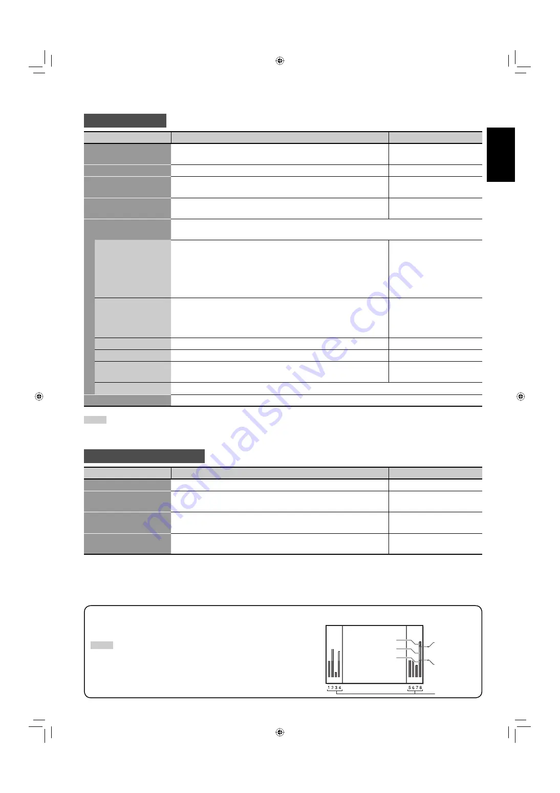
Example of the level meter display 

—Level indication and audio channels

Ex.: When “LEVEL METER ch” is set to “1–8” and ”BAR TYPE” is set to “3COLORS.”

NOTE

•  When “BAR TYPE” is set to “W.100” or “W.50,” the standard input level set in the 

“REFERENCE LEVEL” is displayed with the line indication. Input level set in “OVER 
LEVEL” is not displayed.

•  The audio channel bar with no signal input is displayed in white for the “3COLORS” 

setting, and in gray for other settings.

OVER LEVEL

REFERENCE 
LEVEL

Red

Yellow

Green

Audio channels

06-42_GM-H40L2A-f.indd   23

06-42_GM-H40L2A-f.indd   23

06.4.24   5:20:38 PM

06.4.24   5:20:38 PM

Summary of Contents for GM-H40L2A

Page 1: ...G LCD DISPLAYMONITOR MANUEL D INSTRUCTIONS MONITEUR LCD ISTRUZIONI SCHERMO A CRISTALLI LIQUIDI MANUAL DE INSTRUCCIONES MONITOR PANTALLA LCD LCT1943 002A INSTRUCTIONS GM H40L2A ENGLISH GM H40L2A_cover 4 indd 3 GM H40L2A_cover 4 indd 3 06 4 24 10 46 56 AM 06 4 24 10 46 56 AM ...

Page 2: ...entre Europe GmbH Postfach 10 05 52 61145 Friedberg Allemagne Gentile Cliente Questa apparecchiatura è conforme alle direttive e alle norme europee relative alla compatibilità elettromagnetica e alla sicurezza elettrica Il rappresentante europeo della Victor Company di Japan Limited è JVC Technology Centre Europe GmbH Postfach 10 05 52 61145 Friedberg Germania Apreciado cliente Este aparato cumple...

Page 3: ...INSTRUCTIONS GM H40L2A LCD DISPLAY MONITOR ENGLISH 01_GM H40L2A_EN f indd 1 01_GM H40L2A_EN f indd 1 06 4 24 5 22 42 PM 06 4 24 5 22 42 PM ...

Page 4: ... cause malfunction electric shock or fire Note for United Kingdom power cord only The plug on United Kingdom power cord has a built in fuse When replacing the fuse be sure to use only a correctly rated approved type re fit the fuse cover Consult your dealer or qualified personnel How to replace the fuse Open the fuse compartment with the blade screw driver and replace the fuse IMPORTANT SAFEGUARDS...

Page 5: ... product has been dropped or damaged in any way f When the power supply cord or plug is damaged Do not attempt to service this product yourself as opening or removing covers may expose you to dangerous voltages and other hazards Refer all service to qualified service personnel Do not use this product near water Do not use immediately after moving from a low temperature to high temperature as this ...

Page 6: ...t from the wall outlet and disconnect the cable system Do not overload wall outlets extension cords or convenience receptacles on other equipment as this can result in a risk of fire or electric shock Use only the accessory cord designed for this product to prevent shock When connecting other products such as VCR s and personal computers you should turn off the power of this product for protection...

Page 7: ...is only valid in the European Union Maintenance Unplug this product from the wall outlet before cleaning Screen To avoid irreparable change in appearance of the screen such as uneven color discoloration scratches be careful about the following Do not paste or stick anything with any glues or adhesive tapes Do not write anything on the screen Do not strike the screen with a hard object Avoid conden...

Page 8: ... 40 Specifications 41 Checking the accessories The following accessories are included with the monitor Check for them If any item is missing please contact the dealer where you have purchased the monitor Remote control RM C2006 Power cord x 1 Batteries AA R6 x 2 Ferrite cores x 2 NOTE Be sure to attach the supplied ferrite cores to the speaker cords when using external speakers to reduce interfere...

Page 9: ... 16 ASPECT button Changes the aspect ratio see page 17 DISPLAY button Displays the information of the current input see page 17 5 2 3 buttons Operates the menu see page 19 OK button Enters the password for the Security Lock see page 32 INPUT SELECT buttons Selects the input see page 16 A VIDEO button Selects the input to the VIDEO IN A terminal Input A B RGB COMPO DVI button Selects the input to t...

Page 10: ...Connect external control equipment see pages 14 33 to 37 RS 232C terminal Connect to the RS 232C terminal of a personal computer RS 485 terminals IN terminal Connect external control equipment OUT terminal Connect another component to send out the control signal coming into the IN terminal cascade connection AUDIO OUT terminals Connect external speakers or audio equipment EXT SPEAKER terminal Conn...

Page 11: ...rminal stereo mini jack Connect to the audio output terminals of the equipment connected to the VIDEO IN B terminal VIDEO IN A B terminals Connect video output terminals of equipment such as a VCR see page 15 VIDEO IN A terminal IN terminal BNC Connect to the video output terminals of playback equipment such as a VCR OUT terminal BNC Connect to the video input terminal of another monitor etc Y C I...

Page 12: ...tallation place should be within the range of 0 C to 40 C slightly variable depending on ambient conditions for installation When installing the monitor near the ceiling or similar location the remote control may not work correctly because of possible effects such as reflections from the surroundings If this happens move the monitor where it is free from these effects Do not install the monitor in...

Page 13: ...terminals on the rear panel of the monitor CAUTION Do not short circuit 9 and speaker cords to each other Refer also to the instructions supplied with the speakers NOTE When using the external speakers set SPEAKER SELECT on the main menu to EXT external see page 23 When installing the monitor vertically Make sure to install the monitor in the direction illustrated on the right Set the speed of the...

Page 14: ... 600 37 9 60 3 Non interlace 7 XGA60 1024 768 48 4 60 0 Non interlace 8 WXGA60 1366 768 48 4 60 0 Non interlace 9 WXGA 1280 1280 768 47 8 60 0 Non interlace 10 WXGA 1360 1360 768 47 7 60 0 Non interlace 11 1280 720 1280 720 44 8 60 0 Non interlace 12 XGA70 1024 768 56 5 70 1 Non interlace 13 XGA75 1024 768 60 0 75 0 Non interlace 14 XGA85 1024 768 68 7 85 0 Non interlace 15 XGA 75 3 1152 864 67 5 ...

Page 15: ...though it s frequency is within the acceptable range Depending on the connected equipment the monitor may not be compatible with composite sync Cs or G on sync signals When a preset mode signal is input the signal format is displayed on the screen For other signals the horizontal vertical frequency or resolution is displayed The DVI D terminal can accept only No 3 4 6 11 16 18 and No 19 signals Wh...

Page 16: ...it s plug and pull it out Refer also to the user manual of each piece of equipment Amplifier etc To stereo audio input terminals To RS 232C terminal To RS 485 output terminal To RS 485 input terminal External control input terminal of other equipment See page 33 Stereo audio cable RJ 45 cable RJ 45 cable RS 232C cable External equipment used to control the monitor See pages 33 to 37 To external sp...

Page 17: ...o cable BNC cable Stereo audio cable Connect the VIDEO IN A OUT terminal to the video input terminal of another monitor etc CAUTION Since the IN terminal and OUT terminal are loop through terminals the devices connected to the OUT terminal should be correctly terminated Otherwise pictures become abnormally bright or the display screen gets affected abnormally R L Playback component such as a VCR T...

Page 18: ...n change Inputs A and B quickly see INPUT CONFIGURATION on page 23 Adjusting the volume From the remote control On the main unit When the Control Lock is set to ON see page 29 you cannot use the buttons on the main unit When the Security Lock is in set to ON see page 32 you need to enter the password when turning on the monitor To turn off the volume immediately Pressing the button again resumes t...

Page 19: ... input Out of range appears NOTE When STATUS DISPLAY on the main menu is set to ON see page 25 the status is also displayed in the following cases When you turn on the monitor When you change inputs or When you change signal types INPUT A VIDEO NTSC Current input Input type 2 Input signal format 3 PC input ONLY REAL DOT Displays center portion of the original picture input from the personal comput...

Page 20: ...When the dual display mode is activated the current input is displayed on the main window and the other is displayed on the sub window NOTE The dual display mode is available only when analog RGB signals are being input to Input B For details see page 25 You cannot change the input when the dual display mode is in use To change the inputs for the main and sub windows deactivate the dual display mo...

Page 21: ...press 2 3 to make adjustments 4 Press MENU EXIT to return to the previous menu Pressing the button again exits the menu operation NOTE For some items adjustments will be made by pressing 2 3 in step 2 MENU EXIT SET UP 5 2 3 MENU Works in the same way as MENU EXIT on the remote control SET UP On the main unit 5 Works in the same way as 2 3 on the remote control Selected item Operation guide CO LO R...

Page 22: ... 01 CHROMA 01 PHASE 01 BACK LIGHT HIGH COLOR TEMP 01 SHARPNESS Are yo u sure YES th e n NO th e n MENU re set key key ENG LI SH MENU MENU Menu Configuration MAIN MENU On the main menu you can make various adjustments and settings for picture screen and audio Select the menu language English German French Italian Spanish or Russian Configuration of the main menu screen NOTE Some items may not appea...

Page 23: ... H SIZE Adjusts the horizontal screen size Varies depending on other settings H POSITION Adjusts the horizontal screen position V SIZE Adjusts the vertical screen size V POSITION Adjusts the vertical screen position DOT CLOCK Adjusts to eliminate stripes or flickering when analog RGB signals are being input from a computer Use with CLOCK PHASE Normally no adjustment is needed Varies depending on o...

Page 24: ...VEL OVER L EVEL OFF 3COLORS HIGH 20dB 8dB Are yo u su re YES th e n NO th e n MENU re set key key Are yo u su re YES th e n NO th e n MENU re set key key PI CTURE SETTI NG SIZE SETTING AUDI O SETTI NG I NPUT CO NFI G URATI O N FUNCTI O N SETTI NG LANG UAG E M AI N M ENU ENG LI SH MENU MENU 22 MenuConfiguration MAINMENU cont 1 1When no HD SD SDI or SDI input card option is inserted 2When an HD SD S...

Page 25: ...L Sets the input level s lower limit indicated in red for the 3COLORS display 10dB 8dB 6dB 4dB 2dB reset Restores the default setting for LEVEL METER SETTING reset Restores the default setting for all the items in AUDIO SETTING NOTE The items for EMBEDDED AUDIO setting AUDIO L R ch and LEVEL METER SETTING are displayed on the menu only when the HD SD SDI or SDI input card option is installed INPUT...

Page 26: ... DUAL DISPLAY O FF Are yo u sure YES then NO th en MENU reset key key Are yo u sure YES then NO th en MENU reset key key MULT I SIZE MULT I POSI re se t MULTI DISPLAY 2 2 1 PI CTURE SETTI NG SI ZE SETTI NG AUDI O SETTI NG INPUT CO NFI G URATI O N F UNCTI O N SETTI NG L ANG UAG E M AI N M ENU ENG LI SH MENU MENU 24 MenuConfiguration MAINMENU cont When MODE is PBP When MODE is OFF When MODE is PIP W...

Page 27: ...age 17 OFF ON 1080 1035 Selects a High Definition signal type 1080 60i or 1035 60i for the component signal to view the picture correctly 1080 1035 SUB HOUR METER Displays the hours of current use unit hour You can reset only this item ECO SENSOR Sets the eco sensor which enables you to adjust the brightness of the screen automatically according to the brightness of the room ON OFF reset Restores ...

Page 28: ...INP C POWER ASPECT Are yo u su re YES th e n NO th e n MENU re se t key key Are yo u su re YES th e n NO th e n MENU re se t key key 000 B DRIVE 000 G DRIVE 000 R DRIVE 000 B CUT OF F 000 G CUT OF F 000 R CUT OF F 00 MENU MENU MENU COLOR T EMP NO SYNC F UNCT ION REMOT E SYST EM SECURIT Y LOCK T IMER VCR ADJ SET UP MENU 1 2 ADJUST SELECT EXIT MENU 00 26 Menu Configuration SET UP MENU On the set up ...

Page 29: ...min reset Restores the default setting for all the items in NO SYNC FUNCTION REMOTE SYSTEM Item To do Setting value REMOTE IN SEL Selects the input terminal used for external control D sub9 RJ 45 CNT RJ45 OUT Selects the external control method for RS 485 OUT terminal RS485 IR OUT CNT RJ45 IN Selects the external control method for RS 485 IN terminal RS485 MAKE TRIG SET PORT F1 PORT F5 Assigns the...

Page 30: ... UP M ENU 2 2 1 4 2 5 ON 0 8 1 6 ON 2 1 2 0 O FF FAST HI G H I NT HI G H LEVEL1 STD SXG A G M H40L2 A TIMER PRESENT T IME HOURS MINUT ES 14 25 14 25 TIMER POWER ON T IME HOURS MINUT ES 08 16 08 16 TIMER POWER OF F T IME HOURS MINUT ES 21 20 21 20 Are yo u su re YES th e n NO th e n MENU re se t key key COLO R TEM P NO SYNC FUNCTI O N REM O TE SYSTEM SECURI TY LO CK TIMER VC R ADJ 00 MENU MENU 06 4...

Page 31: ...s on the main unit Setting value ON OFF NOTE You can use the remote control and external control while the control lock is set To release the lock use the remote control POWER ON DELAY Sets the time when the power supply to the monitor s circuits excluding the micro computers starts after the power button is pressed Setting value OFF FAST SLOW NOTE If you are going to turn several monitors on at t...

Page 32: ...e y ke y Are yo u su re YES th e n NO th e n MENU a ll re se t ke y ke y 00 SET UP M ENU 2 2 O FF FAST HI G H I NT HI G H LEVEL1 STD SXG A G M H40L2 A MENU CONTRO L LO CK POW ER O N DELAY SYNC TERM SYNC SELECT COO LI NG M O DE I P SELECT SAM PLI NG M O DE SXG A SXG A r eset all r eset MODEL VER 06 42_GM H40L2A f indd 30 06 42_GM H40L2A f indd 30 06 4 24 5 20 55 PM 06 4 24 5 20 55 PM ...

Page 33: ...Select SXGA when SXGA60 signal is input through the RGB COMPO terminal and SXGA when SXGA 60 or SXGA 60 signal is input through the RGB COMPO terminal This item does not affect other signals and is not displayed for other signals Setting value SXGA SXGA reset Restores the default setting for all the items in the set up menu all reset Restores the default setting for all the items in the main menu ...

Page 34: ... Select SECURITY LOCK OFF on the SECURITY LOCK sub menu of the set up menu 2 Press 3 The password entering screen appears 3 Enter the password See How to enter a password below The Security Lock is set to ON After activating the Security Lock function the password is required to turn on the monitor Enter the password see How to enter a password below If the power on timer see POWER ON SET on page ...

Page 35: ...OUT setting CNT RJ45 IN setting Serial communication RS 485 RJ 45 1 RS485 RS485 RS 232C D sub9 1 RS485 RS485 IR OUT system Any IR OUT Any MAKE system RJ 45 RS485 MAKE TRIG system RJ 45 RS485 TRIG 1For the monitor connected to the external control equipment set REMOTE IN SEL according to the actual connection Set other monitors to RJ 45 NOTE Control priority is as follows MAKE or TRIG trigger syste...

Page 36: ...bits Parity No parity Stop Bits 1 bit Flow Control No control Communication Code ASCII Code RS 232C A straight cable with a RS 232C connector male for the monitor female for the external control equipment Command outline When the monitor is turned on the external control is not ready To start communication send the connection command from the external control equipment To terminate the communicati...

Page 37: ...ting adjustment 3 No data 11 B A D J L Cr Makes setting adjustment 2 No data 12 B E N T E R Cr Enters the password for the Security Lock No data 13 B S E T U P Cr Displays the SET UP MENU No data 14 B P W 1 Cr Turns on the monitor No data 15 B P W 0 Cr Turns off the monitor No data 16 B I N A Cr Selects Input A No data 17 B I N B Cr Selects Input B No data 18 B I N C Cr Selects Input C No data 19 ...

Page 38: ...o Input B Invalid Valid INP C Changes the input to Input C Invalid Valid INP D Changes the input to Input D Invalid Valid INP E Changes the input to Input E Invalid Valid INP F Changes the input to Input F Invalid Valid POWER Turns on off the monitor Power on Power off ASPECT Changes the aspect ratio REGULAR FULL MUTING Turns off or resumes the volume Muting off Muting on PIP Turns on off the PIP ...

Page 39: ...RIG trigger system Operate each function by Pulse control that is short circuiting the corresponding pin terminal to the 8th pin terminal GND for about 1 second NOTE When controlling INP A B C D E F only one terminal must be short circuited Other terminals must be opened When switching PIP and PBP modes open the mode which has been shortcircuited before shortcircuiting the mode you want to make va...

Page 40: ...the main power switch POWER turned on see page 16 The remote control does not work Are the batteries installed correctly see page 6 Are the batteries exhausted Is the front end of the remote control pointing toward the remote sensor Is there any object blocking the path between the remote control and the remote sensor Is the monitor too far away from you Solutions to common problems related to the...

Page 41: ...rate the menu 23 Some items are not shown on the menu Items not available for the current input signal are not displayed Change the input or signal format Some items are displayed only when the corresponding optional input card is inserted PLEASE ENTER PASS ID appears when trying to turn on the monitor The Security Lock is activated Enter the password to turn on the monitor and then deactivate the...

Page 42: ...y improper installation or improper location of the monitor In this case consult your dealer immediately to solve this improper installation and to improve the circumstances around the monitor If TEMP OVER appears in red TEMP OVER will be shown for about two minutes the monitor will shut off automatically then the self diagnostic lamps light in red If this happens switch off the main power using t...

Page 43: ...IDEO IN A Video input BNC terminal x 1 1 V p p 75 Ω Y C terminal x 1 Y 1 V p p 75 Ω C BURST 0 286 V p p 75 Ω for NTSC 0 3 V p p 75 Ω except for NTSC Video output BNC terminal x 1 1 V p p 75 Ω VIDEO IN B RGB COMPONENT input D sub 3 row 15 pin x 1 RGB is compatible with DDC2B Video signal G Y 1 V p p 75 Ω including sync B R PB CB PR CR 0 7 V p p 75 Ω Horizontal sync HD Composite sync Cs HD 0 3 V p p...

Page 44: ...tual products Design and specifications are subject to change without notice IBM and IBM PC are registered trademarks of International Business Machines Corporation Macintosh is registered trademarks of Apple Computer Inc All other product names mentioned herein are used for identification purposes only and may be the trademarks or registered trademarks of their respective companies 1 8 9 16 17 24...

Page 45: ... 2006 Victor Company of Japan Limited 0406MKH MW VP GM H40L2A_cover 4 indd 2 GM H40L2A_cover 4 indd 2 06 4 24 10 46 55 AM 06 4 24 10 46 55 AM ...

Page 46: ...GM H40L2A LCD DISPLAY MONITOR GM H40L2A_BB indd 1 GM H40L2A_BB indd 1 06 4 24 10 48 47 AM 06 4 24 10 48 47 AM ...

Reviews: