background image

1-6 (No.YF079)

SECTION 3

DISASSEMBLY

3.1

BEFORE ASSEMBLY AND DISASSEMBLY

3.1.1 Precautions

• Be sure to disconnect the power supply unit prior to mounting

and soldering of parts.

• Prior to removing a component part that needs to disconnect

its connector(s) and its screw(s), first disconnect the wire(s)

from the connector(s), and then remove the screw(s).

• When connecting/disconnecting wires, pay enough attention

not to damage the connectors.

• When inserting the flat wire to the connector, pay attention to

the direction of the flat wire.

• Be careful in removing the parts to which some spacer or

shield is attached for reinforcement or insulation.

• When replacing chip parts (especially IC parts), first remove

the solder completely to prevent peeling of the pattern.

• Tighten screws properly during the procedures. Unless

otherwise specified, tighten screws at a torque of 0.092N

·

m

(0.94kgf

·

cm). However, as this is a required value at the time

of production, use the value as a measuring stick when

proceeding repair services. (See "SERVICE NOTE" as for

tightening torque.)

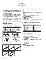
3.1.2 Destination of connectors

3.1.3 Disconnection of connectors (Wires)

Fig.3-1-1

3.1.4 Tools required for disassembly and assembly

Fig.3-1-2

  Torque driver

Be sure to use to fastening the mechanism and exterior parts
because those parts must strictly be controlled for tightening
torque.

  Bit

This bit is slightly longer than those set in conventional torque
drivers.

  Tweezers

To be used for removing and installing parts and wires.

  Chip IC replacement jig

To be used for replacement of IC.

  Cleaning cloth

Recommended cleaning cloth to wipe down the video heads,
mechanism (tape transport system), optical lens surface.

3.2

ASSEMBLY AND DISASSEMBLY OF MAIN PARTS

3.2.1 Assembly and disassembly 

When reassembling, perform the step(s) in reverse order.

(

1) Order of steps in Procedure

When reassembling, preform the step(s) in the reverseorder.
These numbers are also used as the identification (location)
No. of parts Figures. 

(

2) Part to be removed or installed.

(

3) Fig. No. showing Procedure or Part Location.

C = CABINET

(

4) Identification of part to be removed, unhooked, unlocked,

released, unplugged, unclamped or unsoldered.

S = Screw
L = Lock, Release, Hook
SD = Solder
CN = Connector

[Example]

• 4 (S1a) = Remove 4 S1a screws.
• 3 (L1a) = Disengage 3 L1a hooks.
• 2 (SD1a) = Unsolder 2 SD1a points.
• CN1a = Remove a CN1a connector.

(

5) Adjustment information for installation.

CN2a

CN2b

MAIN  CN101

MAIN  CN103

40

10

CONN. No.

PIN No.

CONNECTOR

Two kinds of double-arrows in connection tables respectively

show kinds of connector/wires.

: The connector of the side to remove

: Wire

: Flat wire

: Board to board (B-B)

MONI BW 

CN761

MINI BW 

CN762 

B-B Connector

B-B Connector

B-B Connector

·  Pull the both ends of the board in the direction of the arrow, and remove the B-B Connector.

FPC Connector

Wire

· Pull both ends of the connector in the arrow  


  direction, remove the lock and disconnect the flat  
 wire.

FPC Connector

Lock

Wire

· Extend the locks in the direction of the arrow for  
  unlocking and then pull out the wire. After  


  removing the wire, immediately restore the locks  
  to their original positions because the locks are  
  apt to come off the connector.

Cleaning cloth

KSMM-01

Torque driver

YTU94088

Bit

YTU94088-003

Chip IC replacement jig

PTS40844-2

Tweezers

P-895

(  4)

(  5)

(  2)

(  3)

(  1)

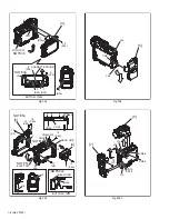
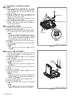
TOP COVER ASSY

UPPER ASSY

(Inc. VF ASSY,

SPEAKER/MONITOR)

E.VF UNIT(B/W)

C1

C2-1

C2-2

4(S1a), 3(L1a),CN1a

(S2a),2(S2b),3(S2c)

2(SD1a),

L2,CN2a,b

2(S8),L8,CN8a

-

-

NOTE 8

[1]

[2]

[8]

STEP

No.

PART

NOTE

Fig.

No.

POINT

Summary of Contents for GE-D240EX

Page 1: ...Y GR D240EZ GR D245EG GR D247EK For disassembling and assembling of MECHANISM ASSEMBLY refer to the SERVICE MANUAL No 86700 MECHANISM ASSEMBLY TABLE OF CONTENTS 1 PRECAUTIONS 1 3 2 SPECIFIC SERVICE INSTRUCTIONS 1 5 3 DISASSEMBLY 1 6 4 ADJUSTMENT 1 15 5 TROUBLE SHOOTING 1 18 GR D240EK GE D240EX GR D240EY GR D240EZ GR D245EG GR D247EK M5D2S2 ...

Page 2: ... 1 6 CCD Lens F 1 8 f 2 2 mm to 55 mm 25 1 power zoom lens Filter diameter Ø27 mm LCD monitor 2 5 diagonally measured LCD panel TFT active matrix system Viewfinder Electronic viewfinder with 0 16 color LCD Speaker Monaural For Digital Video Camera Format DV format SD mode Signal format PAL standard Recording Playback format Video Digital component recording Audio PCM digital recording 32 kHz 4 cha...

Page 3: ...rts 9 When a power cord has been replaced check that 10 15 kg of force in any direction will not loosen it Fig 1 1 2 10 Also check areas surrounding repaired locations 11 Products using cathode ray tubes CRTs In regard to such products the cathode ray tubes themselves the high voltage circuits and related circuits are specified for compliance with recognized codes pertaining to X ray emission Cons...

Page 4: ...g prongs and externally exposed accessible parts Use an AC voltmeter to measure across both terminals of load Z See Fig 1 1 9 and following Fig 1 1 12 Fig 1 1 9 5 Grounding Class 1 model only Confirm specified or lower grounding impedance between earth pin in AC inlet and externally exposed accessible parts Video in Video out Audio in Audio out or Fixing screw etc Measuring Method Connect milli oh...

Page 5: ...lowing table indicate main different points between models GR D240EK GR D240EX GR D240EY GR D240EZ GR D245EG AND GR D247EK MODEL GR D240EK GR D240EX GR D240EY GR D240EZ GR D245EG GR D247EK AC ADAPTER AP V14E AP V17E AP V17E AP V17E AP V17E AP V14E AC CORD BS PLUG NO NO NO NO BS PLUG ...

Page 6: ...nism tape transport system optical lens surface 3 2 ASSEMBLY AND DISASSEMBLY OF MAIN PARTS 3 2 1 Assembly and disassembly When reassembling perform the step s in reverse order 1 Order of steps in Procedure When reassembling preform the step s in the reverseorder These numbers are also used as the identification location No of parts Figures 2 Part to be removed or installed 3 Fig No showing Procedu...

Page 7: ...VER ASSY OP BLOCK ASSY MAIN BOARD ASSY FRAME Z27 ASSY SIELD COVER PR PRE MDA BOARD ASSY MECHA B ASSY GRIP BELT S1 S2a S2b S2c L2a b c d e f S3a 4 S3b CASSETTE COVER S3c S3d L3 CN3 2 S4a 2 S4b L4 CN4 S5a S5b L5a b CN5a b L6a b CN6 S7 L7a b c CN7a b 2 S7b PLATE MIC MIC L7e d FRONT BOARD ASSY CN8a CN8b S9 L9a b CN9a b 3 S10 2 S11 L11 CN12a b c d e f 2 S12 FA1 FA2 FA3 FA4 FA5 1 2 FA6 FA7 FA8 NOTE1a b ...

Page 8: ...c 11 S3d 6 S3b 7 S3b 8 S3b 9 S3b BOTTOM VIEW L3 NOTE3a 5 S3a BOTTOM VIEW 5 4 a CN4 CN4 CN5a CN5a CN5b NOTE5a NOTE5a NOTE5b NOTE5c CN5b 12 S4a 13 S4a 17 S5 15 S4b 14 S4b 16 S5 b c b a c 12 16 L5a REAR UNIT REAR UNIT L4 L4 EJECT SW L5b 6 CN6 L6a L6a 8 a a 7 CN7b CN7a CN8a CN8b 18 S7 L7a L7b L7c ...

Page 9: ... FRONT COVER ASSY PLATE MIC 19 S7b 20 S7b L7e L7d 21 S9 CN9b CN9a 9 L9a L9b FPC SHIELD COVER PR 11 24 S10 22 S10 23 S10 26 S11 25 S11 10 㧦 0 078N㨯m 0 8kgf㨯cm 㧦 0 069N㨯m 0 7kgf㨯cm L11 NOTE11 a b c d e f 13 12 28 S12 27 S12 CN12b CN12c CN12d CN12f CN12e CN12a a b c d e f ...

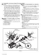
Page 10: ...crews 5 and 6 and remove the COV ER HINGE 5 Remove the two screws 7 and 8 and remove the MON ITOR ASSEMBLY NOTE3b When removing be careful not to damage the FPC ASSEMBLY zDisassembly of MONITOR ASSEMBLY 1 Remove the three screws 9 11 and remove the MON ITOR COVER ASSEMBLY by disengaging the five hooks L3c d e f and g 2 Pull out the U D SWITCH BOARD from the MONITOR CASE ASSEMBLY 3 Release the lock...

Page 11: ...SE ASSY 8 S3c 7 S3c 9 S3d 10 S3d 11 S3d 12 S3d b c b b CN2b CN3c d c MONITOR CASE ASSY MONITOR COVER ASSY MONITOR BOARD ASSY BACKLIGHT ASSY SPACER LCD LCD MODULE SHIELD CASE DIFF SHEET should put this part at right side MONI HINGE ASSY U D SW d a b BOTTOM VIEW SPRING LCD a b b NOTE3b SD3 SD3 㧦 0 98N㨯m 1 0kgf㨯cm ...

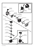
Page 12: ...F zAssembly of CCD BASE ASSEMBLY and CCD BOARD AS SEMBLY 1 Set the OP LPF to the OP BLOCK ASSEMBLY so that the OP side touches the OP BLOCK ASSEMBLY NOTE8a Pay careful attention to the orientation of the OP LPF 2 Set the SHEET to the OP LPF not to come off the right position 3 Attach the SPACER to the OP BLOCK ASSEMBLY 4 Fasten them together with the two screws 1 2 5 Set the CCD BOARD ASSEMBLY in ...

Page 13: ...ocedure be careful not to break the FPC NOTE4c When attaching be careful with the positioning of the LEVER VF and the handling of the FPC zDisassembly of LCD SA LENS SA 1 Remove the two hooks L4c and d on the both sides and remove the LENS SA from the LCD SA NOTE4d Refer to the Fig VF2 for the disassembly of the LCD SA and the LENS SA do not disassemble unless it is needed NOTE4e During the proced...

Page 14: ...LDER LCD GUIDE LCD LCD MODULE CUSHION LCD SHEET POLA 1 SHEET DIFF CASE B LIGHT LEVER VF GUIDE LENS LENS ASSY COMPRESION SPRING SHAFT VF HOLDER EYE SHEET LENS EYE CUP LENS SA LCD SA NOTE4e NOTE4e f NOTE4g NOTE4e NOTE4e NOTE4e NOTE4e NOTE4e L4g L4h L4j L4m L4k L4p L4n LCD SA LENS SA ...

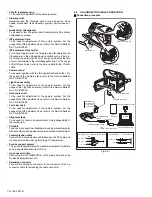
Page 15: ...PC 4 1 2 REQUIRED TEST EQUIPMENT Personal computer for Windows Color TV monitor Oscilloscope dual trace type observable 100MHz or higher frequency The one observable 300 MHz or higher frequency is recommended Digital voltmeter DC power supply or AC adapter Frequency counter with threshold level adjuster 4 1 3 TOOLS REQUIRED FOR ADJUSTMENT Torque driver Be sure to use to fastening the mechanism and...

Page 16: ...For the usage of the INF adjustment lens refer to the Service Bulletin No YA SB 10035 Color bar chart To be used for adjustment of the camera system For the usage of the INF adjustment lens refer to the Service Bulletin No YA SB 10035 Alignment tape To be used for check and adjustment of interchangeability of the mechanism PC cable To be used to connect the Videocamera and a personal computer with...

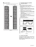
Page 17: ...RICAL ADJUSTMENT Electrical adjustment is performed by using a personal computer and software for SERVICE SUPPORT SYSTEM Read README TXT file to use the software properly As for the connection of cables see 4 2 JIG CONNECTOR CABLE CONNECTION 21 22 23 24 25 26 27 28 29 30 31 32 33 34 35 36 37 38 39 40 EXMOD_1 SYS_TMS SYS_TCK SYS_TDI SYS_TRSTL SYS_TDO SYS_RSTL AL_3VSYS IF_TX JLIP_TX JLIP_RX TXD2 RXD...

Page 18: ...ick screw Reference drawing Fig No Screw tightening torque 1 2 3 4 5 VF1 4 4 VF ASSY 1 2 3 4 5 6 7 8 9 10 11 3 2 4 8 8 O P BLOCK ASSY CCD BOARD ASSY NOTE 㧝 㧖 This mark shows where to attach the screws Do not reuse the screws because the screw lock bond was applied to prevent the screws from loosening Prepare the specified screws and use them in place of the removed screws 㧞 Tightening torque for t...

Page 19: ...ell 2 Though the idler gear and reel disk are engaged with each other the tape is not wound because of overload to the mechanism 3 No FG pulse is output from the reel sensor 4 No power is supplied to the reel sensor 5 Tape transport operation takes place with a cassette having no tape inside 6 The tape slackens and no pulse is produced until the slack is taken up and the tape comes into the normal...

Page 20: ... No YF079 AV MULTIMEDIA COMPANY CAMCORDER CATEGORY 12 3 chome Moriya cho kanagawa ku Yokohama kanagawa prefecture 221 8528 Japan Victor Company of Japan Limited VPT Printed in Japan ...

Page 21: ...YF079 2005 2 GR D240EK GE D240EX GR D240EY GR D240EZ GR D245EG GR D247EK For disassembling and assembling of MECHANISM ASSEMBLY refer to the SERVICE MANUAL No 86700 MECHANISM ASSEMBLY GR D240EK GE D240EX GR D240EY GR D240EZ GR D245EG GR D247EK M5D2S2 SCHEMATIC DIAGRAMS CD ROM No SML200502 ...

Page 22: ... signal path including E E signal path Capstan servo path Drum servo path Example R Y Y Playback R Y signal path Recording Y signal path 6 Indication of the parts for adjustments The parts for the adjustments are surrounded with the circle as shown below 7 Indication of the parts not mounted on the circuit board OPEN is indicated by the parts not mounted on the circuit board R216 OPEN 1 2 3 1 2 3 ...

Page 23: ...OTO_F 10 ZOOM_SW 11 GND 12 REG_3 1V DISCRI EXTDATA5 EXTDATA6 M_VCOCTL ID DSYO3 ADDT10 CLK27B PBLK HDDSC DSCO0 DSYIO5 GND OMT CDRE CDAS ADIN8 CLKI FSPLLCTL REG_3 1V DSYIO3 DSCIO4 DSYIO7 CN113 1 EXMOD_1 21 SYS_TMS 2 SYS_TCK 22 SYS_TDI 3 SYS_TRSTL 23 SYS_TDO 4 SYS_RSTL 24 AL_3VSYS 5 IF_TX 25 JLIP_TX 6 JLIP_RX 26 TXD2 7 RXD2 27 NC 8 I_MTR 28 NC 9 NC 29 ENV_OUT 10 MAIN_VCO 30 ATFI 11 HID 31 DISCRI 12 F...

Page 24: ...UTO DIAL_MANU M_RVS MONI_SW KEY_A KEY_C MENU_SW GND GND REG_4 8V REG_4 8V REG_3 1V LCD_CTL REG_4 8V AU_LV_OUT LCD_CS AU_LV_CLK VDCVF HDCVF MON_G MON_R MON_B GND GND GND GND TPA TPB GND Y_OUT TPA C_OUT V_OUT AU_SIG L AU_SIG R P_DET TPB CN110 QGF0545F1 26X 1 2 3 4 5 6 7 8 9 10 11 12 13 14 15 16 17 18 19 20 21 22 23 24 25 26 HRP D_BATT GND SYS_TMS SYS_RSTL AL_3VSYS SYS_TDO CVF_B JLIP_TX SYS_TRSTL ENV...

Page 25: ...LY 129 MXDT_OUT 24 MMC_L 22 USBDOWN 23 DSC_STS 170 CAPT_REQ 79 FLSH_RST 169 DSC_WKUP 80 DSC_RST 51 LENS_LED 20 EEP_CS 177 REG_CS 186 FZ_CS 104 CDS_CS 149 TG_CS 204 RTC_CS R1074 3 3K I_MTR C1042 0 1 C1012 0 01 R1072 3 3K AL_3 1V TL1035 CDS_CS R1025 47K SPA TL1028 R1080 100K BUZZER R1021 330K R1097 1K BLKA BLKC BLKB TL1001 TL1006 TG_CS TL1004 REGRTC_CLK R1105 1K R1024 3 3K R1059 12K R1048 100K R1067...

Page 26: ...IDAT2 L2653 R2213 2 7 L2603 NQR0269 013X REG_3 1V R2208 22k L2601 NQR0269 013X T C2406 10 6 3 C2612 1 R2209 22k Q2201 DTC144EE X A_MUTE T C2401 10 6 3 T C2402 10 6 3 R2609 22k C2610 L_MUTE R2204 150k C2611 1 C2656 0 047 R2207 33k C2623 10p C2624 10p R2206 33k R2211 820 R2233 560k Q2202 UMX1N W 2 1 4 5 3 6 R2235 3 3k R2210 820 R2234 560k C2225 NRSA6AJ 0R0W C2226 NRSA6AJ 0R0W C2227 NRSA6AJ 0R0W C222...

Page 27: ...1 59 DSYO2 242 DSYO3 155 DSYO4 60 DSYO5 321 DSYO6 322 DSYO7 243 VCC 156 ADD_VSS 61 ADD_VDDE 244 DSCO0 157 DSCO1 324 DSCO2 323 DSCO3 62 DSCO4 245 DSCO5 158 DSCO6 63 DSCO7 64 ADD_VDDL 159 ADD_VSS 246 ADD_VDDE 65 DSYIO0 325 DSYIO1 328 DSYIO2 160 DSYIO3 247 DSYIO4 66 DSYIO5 161 DSYIO6 248 DSYIO7 327 ADD_VSS 67 ADD_VDDE 326 DSCIO0 162 DSCIO1 249 DSCIO2 68 DSCIO3 163 DSCIO4 250 DSCIO5 69 DSCIO6 329 DSCI...

Page 28: ...122 VRM 153 VRL 37 VRH 84 CIN 123 VDD 8AD 38 VSS 8AD 85 VSS 171 NC 172 NC 173 NC 174 NC 175 NC 53 NC 64 NC 75 NC 86 NC 154 VCCQ 87 CSI0 42 CSI1 124 VSSQ 125 CSI2 88 CSI3 155 VCCQ 43 VDD I O 126 CSI4 89 VSS 44 VDD CORE 127 CSI5 156 VSSQ 90 CSI6 45 CSI7 128 INH 91 INV 46 VDD CORE 157 VSS 129 VDD I O 158 VCC 47 VSS 92 YSI0 48 VDD CORE 93 YSI1 130 VSSQ 49 YSI2 94 YSI3 131 VCCQ 50 YSI4 95 YSI5 159 VSSQ...

Page 29: ...0 XAHD 31 XAVD 32 OBCLP 33 WEN 34 ID 35 CLK27 CLK1716 36 Vdd6 37 CLK13 CL 38 TEST 39 VM 40 V2 41 V4 42 V1 43 VH 44 V3 45 SUB 46 VL 47 Vss6 48 RST 0 1 C5501 C5510 0 1 CLKI C5513 0 1 R5509 10 C5512 0 1 L5503 NQR0129 002X R5501 1K 0 1 C5507 VDIN GND REG CCD T C5517 10 16 0 1 C5505 R5508 10 CAM_CLK R5505 10 R5504 10 T C5516 4 7 25 1SS355 X D5501 R5510 100K X5501 NAX0587 001X 1 CTL 2 GND 3 OUT 4 VDD PB...

Page 30: ...5 10k REC_ADJ C4909 0 01 R4960 4 7 C4920 OPEN R4944 C4922 0 1 C4912 0 1 CH C4957 22p C4906 0 1 L4902 NQL38DK 100X 10u IC4901 JCY0215 X 1 2 11 54 12 13 22 63 23 24 33 72 34 35 44 45 T C4954 10 6 3 CH C4915 120p R4952 1k VOI_IN L4955 NQL38DK 100X 10u ASPECT FSPLLCTL Z_PTR_AD R4951 1k CAM_CLK REG_3 1V T C4902 10 6 3 T C4956 10 6 3 OPEN R4903 8 2k R4911 100 T C4904 10 6 3 VD_F Z C4913 0 1 IRIS_PS IR_O...

Page 31: ...OPEN D6502 RB480Y W 1 2 3 4 D6001 RB715W X 2 1 3 AL_3 1V GND LIT_3V CHRG_EVR L6502 NQL38DK 100X C6504 OPEN REG_3 1V C6704 0 0047 R6714 4 7k TL6001 R6709 110k C6703 OPEN R6708 15k R6716 8 2k R6715 4 7k R6513 2 7k C6204 220p R6204 8 2k R6512 47k C6509 0 033 R6103 8 2k R6802 4 7k R6104 R6803 1k C6104 680p C6804 0 0039 C6009 0 22 Q6201 QS6U24 W 1 A 2 S 3 G 4 D 5 NC 6 CA Q6101 QS6U24 W 1 A 2 S 3 G 4 D ...

Page 32: ...VCC1 44 GND 45 VSync 46 HSync 47 Rin 48 Gin L7801 22u L7802 22u T C7801 10 6 3 T C7803 10 6 3 C7802 0 1 C7804 0 1 R7729 120k R7730 120k R7731 120k R7801 C7807 1 C7805 1 C7806 1 C7708 4 7 16 HDCVF VDCVF R7802 C7808 C7809 C7810 C7811 REG_12V L7702 22u C7812 0 1 C7813 2 2 C7814 2 2 C7815 2 2 R7803 6 2K R7804 15K C7816 2 2 C7817 1500P AU_LV_OUT AU_LV_CLK VF_CS TO CPU TO MAIN IF CN110 CPU AUDIO C7818 R...

Page 33: ...eplacement replace the CCD base assembly in whole because it cannot be replaced alone CN302 QGF0517F2 20X 1 REG_3 1V 2 REG_3 1V 3 REG_4 8V 4 REG_4 8V 5 LCD_CTL 6 REG_4 8V 7 AU_LV_OUT 8 LCD_CS 9 AU_LV_CLK 10 VDCVF 11 HDCVF 12 MON_G 13 MON_R 14 MON_B 15 HRP 16 M_RVS 17 GND 18 GND 19 GND 20 GND S305 NSW0198 001X STOP 1 2 S304 NSW0198 001X REW 1 2 S302 NSW0198 001X PLAY 1 2 S303 NSW0198 001X LIGHT 1 2...

Page 34: ...D S_RL REEL_VCC T_RL GND T_RL S_SENS MIC3 MIC2 MIC1 E_SENS QGF0505F2 16X UPPER CONTACT 1 2 3 4 5 6 7 8 9 10 11 12 13 14 15 16 DEW_SENS P R_GND LOAD_FWD LOAD_FWD LOAD_REV LOAD_REV QGF0505F2 06X UPPER CONTACT 1 2 3 4 5 6 HG_U HG_V HG_W HG_BS HG_BS HG_W HG_V HG_U C_COIL_V C_COIL_V C_COIL_U C_COIL_U C_COIL_W C_COIL_W MDA_2 9V C_FG GND C_FG QGF0534F1 18X UNDER CONTACT 1 2 3 4 5 6 7 8 9 10 11 12 13 14 1...

Page 35: ...µ 10 LOAD_REV LOAD_FWD C1601 0 01 C1630 0 22 C1629 0 22 C1623 0 047 C1622 0 022 GND C1607 0 047 R1620 68K R1621 10K R1629 560K C1636 0 01 C1635 0 01 C1634 0 01 D1603 DAP222 X R1635 3 3K R1636 12K R1637 150K C1633 0 47 DRUM_PWR DRUM_ERR GND CAP_ERR CAP_PWR M_UNREG M_REG3 1 HG_BS HG_BS F1602 NMFZ007 R50X K F1601 NMFZ007 R20X K R1611 390 R1610 390 MDA_2 9V D1604 DAP222 X C1632 0 47 L1601 NQL382M 100X...

Page 36: ...D L3502 NQL402M 100X REG_4 8V REG_3 1V IC3502 SN74AHC1G04K X OPEN 1 2 3 4 5 R3501 470 R3502 100k R3503 1k R3504 240 R3505 240 R3506 240 R3507 240 R3508 22k R3509 OPEN R3510 OPEN R3512 0 C3526 0 01 C3504 0 047 C3505 0 022 C3506 1 C3507 0 01 C3508 0 01 C3509 0 01 C3510 0 1 C3511 0 01 C3512 0 1 C3513 0 1 C3514 0 047 C3515 0 047 C3516 0 047 C3517 0 01 C3518 0 01 C3519 0 001 C3520 0 01 C3521 0 1 C3522 ...

Page 37: ...2 0 C7607 1 T7501 NQS0060 001X 10 6 5 1 4 3 2 IC7602 1 2 3 4 5 C7618 C7619 1 R7601 0 L7604 R7602 C7617 L7602 D7605 RB521S 30 X C7622 R7608 10M C7621 C7602 R7612 R7613 R7614 CN7602 QGF0528F1 40X 1 VCOMH 2 VCOML 3 VCL 4 C41N 5 C41P 6 VGH 7 C31N 8 C31P 9 VGL 10 C23N 11 C23P 12 C22N 13 C22P 14 C21N 15 C21P 16 VDDA 17 VFB 18 DRV 19 VSS 20 NC 21 VDD 22 VDD1 23 NC 24 VSS1 25 VCOIN 26 PDO 27 VA R 28 VB G ...

Page 38: ...RS X R703 390 CN701 TO MAIN IF CN103 QGF0543F1 17X 1 IR_OUT 2 REG_4 8V 3 IR_RMC 4 EM_GND 5 EM_DET_L 6 EXT L 7 EXT R 8 EM_GND 9 GND 10 GND 11 GND 12 REG_4 8V 13 REG_4 8V 14 LAMP_ON 15 MONI_SW 16 LITHIUM 17 EJT_SW R704 1 8k R703 R710 NO EXT MIC EXCHANGE PARTS LIST WEAR EXT MIC NO WEAR WEAR C705 C706 NO WEAR WEAR NO WEAR NO WEAR NO WEAR D702 D703 NO WEAR WEAR NO WEAR J701 WEAR D701 LED WEAR L702 L703...

Page 39: ...0147001a_rev0 1 VF SCHEMATIC DIAGRAM NOTES 1 For the destination of each signal and further line connections that are cut off from this diagram refer to BOARD INTERCONNECTIONS 2 The parts with marked is not used WIDE PHOTO TELE PLAY OFF AUTO MENU TRIG ZOOM UNIT 12 REG_3 1V 11 GND 10 ZOOM_SW 9 PHOTO_F 8 DIAL_PB 7 DIAL_OFF 6 DIAL_AUTO 5 DIAL_MANU 4 GND 3 PWR_LED 2 GND 1 TRIG_SW TO MAIN IF CN109 ZOOM...

Page 40: ... 43 44 86 IC1002 1 10 11 20 IC4951 1 12 13 24 25 36 37 48 IC3201 IC8001 L3701 L4954 L4955 R3719 CN111 R1132 R1044 C7705 TL3201 R1003 R1005 R1010 R1012 R1013 R1014 R1015 R1016 R1017 R1018 R1019 R1022 R1025 R1029 R1032 R1033 R1034 R1036 R1048 R1049 R1057 R1060 R1061 R1063 R1064 R1066 R1067 R1068 R1070 R1072 R1073 R1074 R1075 R1076 R1077 R1078 R1080 R1082 R1083 R1088 R1089 R1090 R1091 R1092 R1093 R10...

Page 41: ...RA1004 RA3007 RA3008 RA3009 RA3010 RA3011 RA3012 L8610 X3001 X8601 C4907 IC3002 1 4 5 8 IC8601 C4908 C4909 C4910 F6001 C4911 L3004 L6001 L6501 C4912 C4913 C4914 C4915 C4916 C102 R1147 R1148 TL3016 C4917 C4918 C4920 C4921 C4922 R3720 R3721 R2618 CN114 D102 R101 CN103 1 1 4 17 R3077 C7718 RA8601 RA8602 C7719 RA8606 R1031 R1035 R1043 R1045 R1047 C7720 R1115 R1116 R3001 R3002 R3006 C3018 C3074 R3018 R...

Page 42: ... R3514 R3515 C3532 R1601 R1602 R1610 R1611 R1612 R1613 R1616 R1621 R1624 R1625 R1629 R1632 R1633 R1634 R1635 R1636 R1701 R1706 R1709 R1710 R3502 R3504 R3505 R3506 R3507 R3509 R3510 C1601 C1615 C1616 C1617 C1618 C1619 C1620 C1624 C1626 C1627 C1634 C3507 C3509 C3510 C3512 C3513 C3514 C3517 C3518 C3519 C3520 C3521 C3523 C3524 C3527 C1628 C1632 C3506 L3502 L3501 L3503 L3504 L3505 C1602 C3501 C3502 C35...

Page 43: ...3 ZP1 5 ZP2 25 ZP2 26 ZP1 6 ZP1 17 ZP1 19 ZP2 37 R7608 R7605 R7607 R7609 R7610 R7611 R7612 R7613 R7502 R7503 C7502 C7621 R7614 C7613 C7615 C7618 C7622 C7603 C7604 C7605 C7606 C7619 C7607 C7608 C7610 C7611 C7612 C7620 C7504 C7505 C7503 L7602 C7602 Q7501 Q7502 Q7503 Q7504 IC7602 1 3 4 5 L7601 CN7601 20 1 D7604 L7603 L7501 CN701 J701 D702 D703 IC701 Q701 R702 R703 R704 R705 R706 R708 L702 L703 C701 C...

Page 44: ...1 BATT_CHK ADP_L T_BATT ADP_DC IC7601 AUDIO Q2401 Q2403 IC2201 REG_3 1V BATT_ 22 25 36 40 REG CCD LITHIUM 3 1 2 REG_4 8V OP DRV M_REG4 8 M_UNREG CAP_PWR DRUM_PWR M_REG4 8 CN102 23 6 5 ZOOM UNIT IC1701 IC1702 CN406 SENSOR 3 IC3501 21 REG_2 5V REG_3 1V REG_4 8V CN104 CN401 IC4901 L4954 IC4951 Z_VCC F_VCC F_LED MONITOR 31 35 22 25 36 40 3 1V REG Q6101 REG_3 1 V REG_12V REG_3 1V REG_1 7V IC3701 Q3702 ...

Page 45: ...ADIN 0 9 REC_DATA ATFI TPA TPB T_F_V_RST CAM_CLK CAM_OUT RTC_IN VOI_CLK VOI_OUT OSD_CS EEP_IN EEP_OUT H1 H2 V1 V4 CN5001 CN5001 CN101 CN108 CN7001 CN7002 CN402 10 13 15 18 T_F_V_RST IRIS_CS IRIS_PS 2S 2F 1S 1F 17 17 CCD_OUT H1 H2 9 12 10 9 12 10 CN107 1 4 1 4 AGC_OUT 18 24 30 23 17 11 CN104 CN401 REAR UNIT PRE MDA 3 0 TG_CS T_F_V_RST CAM_CLK CAM_OUT PARAGON IC3001 1 4 CN102 20 21 DSP_RST DSP_CS RE...

Page 46: ...30 0 2 0 2 31 0 1 0 32 2 9 0 33 3 0 3 0 34 1 5 0 35 0 0 36 3 0 3 0 37 0 0 38 0 0 39 0 0 40 0 2 0 41 7 3 0 42 0 2 14 9 43 14 8 14 9 44 7 3 14 9 45 7 3 14 9 46 7 8 7 7 47 0 0 48 0 3 0 IC6001 1 0 0 2 7 6 7 6 3 0 0 4 8 9 8 9 5 0 0 6 8 0 8 0 7 9 5 9 5 8 7 6 7 6 9 6 1 6 1 10 0 0 11 10 6 10 6 12 11 7 11 7 13 8 3 8 3 14 1 2 1 1 15 0 7 0 7 16 1 0 1 0 17 0 0 18 3 1 3 0 19 10 8 10 8 20 10 8 10 8 21 0 0 22 0 ...

Page 47: ...39 1 5 1 4 40 0 0 41 0 0 42 0 0 43 0 0 44 0 0 45 4 8 4 7 46 1 5 1 4 47 1 5 1 4 48 1 5 1 5 49 1 5 1 5 50 0 0 51 13 7 13 7 52 2 3 2 3 53 12 3 12 3 54 0 0 55 0 0 56 0 0 57 3 0 3 0 58 2 9 2 9 59 0 0 60 1 1 1 1 61 0 3 0 2 62 1 5 1 5 63 0 6 0 6 64 0 9 0 9 IC1701 1 2 1 4 1 4 3 1 4 1 4 4 0 0 5 1 4 1 4 6 1 3 1 4 7 8 4 8 4 8 IC1702 1 0 3 0 2 1 3 1 4 3 4 0 0 5 6 1 4 1 4 7 8 4 8 4 8 IC3501 Q1601 1 0 0 2 0 0 3...

Page 48: ... No YF079 AV MULTIMEDIA COMPANY CAMCORDER CATEGORY 12 3 chome Moriya cho kanagawa ku Yokohama kanagawa prefecture 221 8528 Japan Victor Company of Japan Limited VPT Printed in Japan ...

Page 49: ...ty and performance We recommend that genuine JVC parts be used 1 EXPLODED VIEW 1 1 FINAL ASSEMBLY M1 The instruction manual to be provided with this product will differ according to the destination 117 114 116 106 115 124 123 122 121 133 120 120 120 118 119 125 107 202 201 203 202A F2 F2 c c d d b b a a F1 F1 117 VF ASSEMBLY M3 MONITOR ASSEMBLY M4 GR D240EZ GR D240EY GR D240EX MODEL GR D240EK A MA...

Page 50: ...309 309 304 309 310 305 310 310 300 113 505 503 502 504 505 205 206 502B 502B 502B 502A e e F5 F4 F5 F4 F6 W2 W2 h h F9 F10 F11 F12 F13 F9 F10 F11 F12 F13 F14 F14 F6 f 310 g g f F3 W1 F3 W1 502B 308 602 CCD BOARD ASSEMBLY 02 FRONT BOARD ASSEMBLY 07 MECHANISM ASSEMBLY M2 ASSEMBLY 03 ASSEMBLY 01 136 602D 602E 602E 602F 602F 602E 602C 602E 602A 602E 602E 602B 610 610 699 ...

Page 51: ...932 947 948 946 966 945 944 959 958 960 941 957 955 952 953 953 931 937 937 925 924 937 928 929 954 935 961 963 965 BB AA AA AA CC AA CC CC CC CC AA AA 930 AA 976 979 934 900 AA 936 YMA0029AA YMA0029BG 998 CC RX 410R Grease HANARL BB is not contained in 900A NOTE2 Mark indicate lubrication and greasing areas NOTE1 The section marked in AA BB and CC YTU94027 Oil AA KYODO SH JB Grease Symbol in draw...

Page 52: ... YF079 1 3 VF COLOR ASSEMBLY M3 708 719 709 720 723 711 710 707 725 726 727 728 729 730 731 732 733 799 715 714 702 705 705 a a 724 704 704 711A 700 703 VF BOARD ASSEMBLY 08 798 798C 798B 798A 798D 798E 798F ...

Page 53: ...808 813 815 803 816 816 816 823 823 817 822 OPE BOARD 04 825 821 820 824 824 817B 817G 817D 817C 817B 817F 817B 817A 817E 807 812 809 811 811 810 F1 F1 a a b b 817H 817H 818 c c 819 819 F2 d d 800 F4 F3 F4 F3 F2 MONITOR BOARD ASSEMBLY 06 803A 817J ASSEMBLY 898 ...

Page 54: ...3 6 No YF079 1 5 PACKING AND ACCESSORY ASSEMBLY M5 003 004 005 060 063 LABEL SERIAL FINAL ASSEMBLY M1 051 061 058 056 001 006 002 008 053 052 062 059 007 054 ...

Page 55: ...01A WASHER x2 699 LY30034 0S5A SPACER A Symbol No Part No Part Name Description Local 900 YMA0029BG MECHA A ASSY Y E Y08173 900A YMA0029AA MECHA A ASSY JVM BJVC 901 LY32870 001Q CASSETTEHOUSING ASSY 902 YQ43893 8 MINI SCREW x3 903 LYH30420 001A UPPER BASE ASSY 904 QYSPSPU1425M SCREW M1 4 x 2 5mm 905 YDV2102E DRUM ASSY M B SET022 906 LY44533 001A DAMP SCREW ASSY JVM BJVC x2 907 LY44533 002A DAMP SC...

Page 56: ...Y30034 0S7A SPACER A Symbol No Part No Part Name Description Local Symbol No Part No Part Name Description Local 001 LY34452 001A POLY BAG DOCUMENT 002 LYT1380 001A INST BOOK EN ENGLISH A 002 LYT1380 003A INST BOOK FR FRENCH B 002 LYT1380 004A INST BOOK DU DUTCH B 002 LYT1380 005A INST BOOK SP SPANISH B 002 LYT1380 006A INST BOOK IT ITALIAN B 002 LYT1380 015A INST BOOK PT PORTUGUESE B 002 LYT1380 ...

Page 57: ...SISTOR Q7706 XP4311 W TRANSISTOR Q7706 or UMD3N W DIGI TRANSISTOR D101 EMZ6 8N X Z DIODE BATT DC D102 MA8068 X Z DIODE BATT DC D1001 DA221 X DIODE ARRAY D1001 or MA133 X SI DIODE D1002 1SS376 X SI DIODE D3001 RB551V 30 X SB DIODE PHY VDD D3002 EC2C01C TR X VARI CAP DIODE FS VCO D3003 EC2C01C TR X VARI CAP DIODE FS VCO D3004 EC2C01C TR X VARI CAP DIODE MAIN VCO D3005 DAN222 X SI DIODE D3005 or MA13...

Page 58: ...3W C CAPACITOR 0 01uF 16V K Symbol No Part No Part Name Description Local C3066 NCBA1CK 103W C CAPACITOR 0 01uF 16V K C3067 NCBA1CK 103W C CAPACITOR 0 01uF 16V K C3068 NCBA1CK 103W C CAPACITOR 0 01uF 16V K C3069 NCBA1CK 103W C CAPACITOR 0 01uF 16V K C3070 NCBA1CK 103W C CAPACITOR 0 01uF 16V K C3071 NCBA1AK 104W C CAPACITOR 0 1uF 10V K C3072 NCBA1AK 104W C CAPACITOR 0 1uF 10V K C3073 NCBA1AK 104W C...

Page 59: ...o Part Name Description Local C7802 NCBA1AK 104W C CAPACITOR 0 1uF 10V K C7803 NBE20JM 106X TA E CAPACITOR 10uF 6 3V M C7804 NCBA1AK 104W C CAPACITOR 0 1uF 10V K C7805 NCB30JK 105X C CAPACITOR 1uF 6 3V K C7806 NCB30JK 105X C CAPACITOR 1uF 6 3V K C7807 NCB30JK 105X C CAPACITOR 1uF 6 3V K C7812 NCBA1AK 104W C CAPACITOR 0 1uF 10V K C7813 NCB21AK 225X C CAPACITOR 2 2uF 10V K C7814 NCB21AK 225X C CAPAC...

Page 60: ...A6AJ 332W MG RESISTOR 3 3kΩ 1 16W J Symbol No Part No Part Name Description Local R3012 NRSA6AJ 821W MG RESISTOR 820Ω 1 16W J R3013 NRSA6AJ 332W MG RESISTOR 3 3kΩ 1 16W J R3014 NRSA6AJ 821W MG RESISTOR 820Ω 1 16W J R3021 NRSA6AJ 822W MG RESISTOR 8 2kΩ 1 16W J R3022 NRSA6AJ 822W MG RESISTOR 8 2kΩ 1 16W J R3025 NRSA6AJ 121W MG RESISTOR 120Ω 1 16W J R3026 NRSA6AJ 102W MG RESISTOR 1kΩ 1 16W J R3028 NR...

Page 61: ...ESISTOR 1 5kΩ 1 16W J R6708 NRSA6AJ 153W MG RESISTOR 15kΩ 1 16W J R6709 NRSA6AJ 114W MG RESISTOR 110kΩ 1 16W J Symbol No Part No Part Name Description Local R6710 NRSA6AJ 124W MG RESISTOR 120kΩ 1 16W J R6712 NRSA6AJ 561W MG RESISTOR 560Ω 1 16W J R6713 NRSA6AJ 104W MG RESISTOR 100kΩ 1 16W J R6714 NRSA6AJ 472W MG RESISTOR 4 7kΩ 1 16W J R6715 NRSA6AD 472W MG RESISTOR 4 7kΩ 1 16W D R6716 NRSA6AJ 822W ...

Page 62: ...X C CAPACITOR 0 01uF 25V K C1602 NBE20JM 106X TA E CAPACITOR 10uF 6 3V M C1603 NBE20JM 106X TA E CAPACITOR 10uF 6 3V M C1605 NCB31CK 104X C CAPACITOR 0 1uF 16V K C1606 NCB31HK 152X C CAPACITOR 1500pF 50V K C1607 NCB31CK 473X C CAPACITOR 0 047uF 16V K C1614 NBE21AM 106X TA E CAPACITOR 10uF 10V M C1618 NCB31HK 222X C CAPACITOR 2200pF 50V K C1619 NCB31HK 222X C CAPACITOR 2200pF 50V K C1620 NCB31HK 22...

Page 63: ...QGF0517F2 20X CONNECTOR MONITOR FFC FPC 1 20 S301 NSW0198 001X TACT SWITCH MENU S302 NSW0198 001X TACT SWITCH PLAY S304 NSW0198 001X TACT SWITCH REW S305 NSW0198 001X TACT SWITCH STOP S306 NSW0198 001X TACT SWITCH FF OT1 LY30034 0P2A SPACER A x3 Symbol No Part No Part Name Description Local Symbol No Part No Part Name Description Local PW1 LYA10019 02B1 MONITOR BOARD ASSY IC7601 DN8797MS X IC Q750...

Page 64: ... 2SC4738 YG X TRANSISTOR Q7001 or 2SD2216J QR X TRANSISTOR Q7001 or BC847BT X TRANSISTOR D7001 E1S35AW0C501 X LED C7001 NCB31CK 104X C CAPACITOR 0 1uF 16V K C7002 NCB31CK 104X C CAPACITOR 0 1uF 16V K C7003 NDC31HJ 101X C CAPACITOR 100pF 50V J C7004 NDC31HJ 101X C CAPACITOR 100pF 50V J R7001 NRSA63D 682X MG RESISTOR 6 8kΩ 1 16W D R7002 NRSA63D 272X MG RESISTOR 2 7kΩ 1 16W D R7003 NRSA63D 820X MG RE...

Reviews: