1-10 (No.YF079)
3.2.3 DISASSEMBLY of [3] MONITOR ASSEMBLY
z
CAUTIONS
(1) Remove the MONITOR ASSEMBLY from the UPPER
CASE ASSEMBLY first, as they are removed together in
main parts disassembly, and then proceed to the disas-
sembly procedure.
(2) During the procedure, be careful in handling the LCD
MODULE and other parts. Pay special attention not to
damage or soil the monitor screen.
If fingerprints are left on the screen, wipe them with clean
chamois leather or a cleaning cloth.
(3) Since the BACKLIGHT is soldered to the BOARD AS-
SEMBLY (SD3), they should be removed together ex-
cept for the replacement.
z
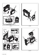
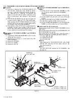
Removing MONITOR ASSEMBLY
(1) Remove the screw (1), and remove the BKT (OPE).
(2) Remove the two screws (2 and 3).
(3) Remove the screw (4), free the OPE BOARD ASSEM-
BLY, and pull out the FPC from the connector (CN2a).
NOTE3a:
Although the MONITOR ASSEMBLY can be removed
with the FPC attached to the OPE BOARD ASSEM-
BLY, remove the OPE BOARD ASSEMBLY consider-
ing the workability and the cut/ break of FPC.
(4) Remove the two screws (5 and 6), and remove the COV-
ER HINGE.
(5) Remove the two screws (7 and 8), and remove the MON-
ITOR ASSEMBLY.
NOTE3b:
When removing, be careful not to damage the FPC
ASSEMBLY.
z
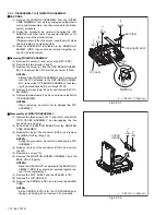
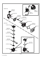
Disassembly of MONITOR ASSEMBLY
(1) Remove the three screws (9-11), and remove the MON-
ITOR COVER ASSEMBLY by disengaging the five
hooks (L3c,d,e,f and g).
(2) Pull out the U/D SWITCH BOARD from the MONITOR
CASE ASSEMBLY.
(3) Release the lock of the connector (CN3b), and remove
the HINGE UNIT by lifting it up.
NOTE3c:
During the procedure, be careful in handling the FPC
ASSEMBLY.
(4) Release the lock of the connector (CN3c), and pull out
the FPC.
(5) Remove the screw (12).
(6) Remove the MONITOR BOARD ASSEMBLY and the
BACK LIGHT together.
NOTE3d:
Since the BACKLIGHT is soldered to the BOARD AS-
SEMBLY (SD3), they should be removed together ex-
cept for the replacement.
(7) Remove the DIFF. SHEET and the SPACER (LCD).
(8) Remove the LCD MODULE.
(9) Remove the SPRING (LCD), and remove the SHIELD
CASE.
NOTE3e:
As the SPRING (LCD) is for the LCD MODULE posi-
tioning and holding, do not remove it if not needed.
Fig.3-2-3-1
Fig.3-2-3-2
OPE BOARD ASSY
FPC ASSY
4
(S3b)
3
(S3b)
2
(S3b)
1
(S3a)
BKT(OPE)
CN3a
NOTE3a
L3a
L3b
㧦
0.98N
㨯
m (1.0kgf
㨯
cm)
COVER
(HINGE)
5
(S3)
6
(S3)
㧦
0.98N
㨯
m (1.0kgf
㨯
cm)


