background image

9

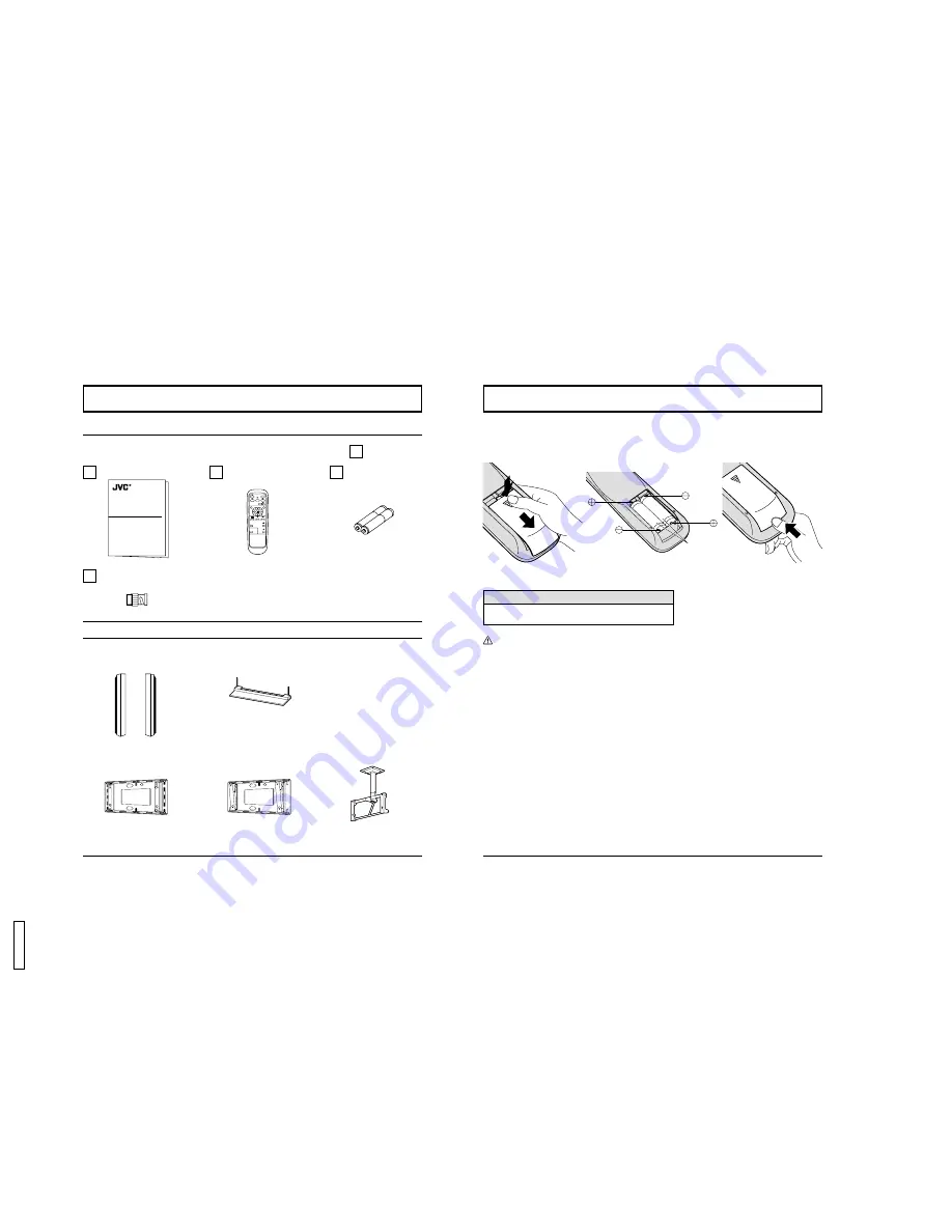
Accessories

Accessories Supplied

Optional Accessories

PLASMA DISPLAY

INPUT

SURROUND

VOL

N

R

PICTURE

SOUND

SET UP

ASPECT

PICTURE
POS. /SIZE

OFF TIMER

PC

GD-V500PZU

Operating Instruction book

Remote Control Transmitter
EUR646526

Batteries for the Remote
Control Transmitter
(AA(R6) Battery 

×

 2)

 Speakers

TS-C5000SPG

 Stand Unit

TS-C50P1G

 Wall Mounting Unit

TS-C50P6G

 Wall Mounting Unit

(angled)
TS-C50P2G

 Ceiling Suspension Unit

TS-C50P3G

RCA/BNC Adapter Plug

For assembling
Full instructions are supplied with each optional accessories for use with this Plasma Display Monitor.

10

Remote Control Batteries

Requires two AA batteries.
1. Turn the transmitter face down.

Press and slide off the battery
cover.

2. Install the batteries as shown in

the battery compartment.
(Po or – must match the
markings in the compartment).

Two "AA" size

Helpful Hint:

For frequent remote control users, replace old batteries with
Alkaline batteries for longer life.

 Precaution on battery use

Incorrect installation can cause battery leakage and corrosion that will damage the remote control transmitter.
Observe the following precautions:
1. Batteries should always be replaced as a pair. Always use new batteries when replacing the old set.
2. Do not combine a used battery with a new one.
3. Do not mix battery types (example: “Zinc Carbon” with “Alkaline”).
4. Do not attempt to charge, short-circuit, disassemble, heat or burn used batteries.
5. Battery replacement is necessary when the remote control acts sporadically or stops operating the Plasma Display.

3. Replace the cove and slide in

reverse until the lock snaps.

8

GD-

V

500PZ

U

Summary of Contents for GD V500PZU

Page 1: ...point within a triangle is intended to tell the user that important operating and servicing instructions are in the papers with the appliance WARNING 1 To prevent electric shock do not remove cover No user serviceable parts inside Refer servicing to qualified service personnel 2 Do not remove the grounding pin on the power plug This apparatus is equipped with a three pin grounding type power plug ...

Page 2: ...ent of the obsolete outlet 10 Protect the power cord from being walked on or pinched particularly at plugs convenience receptacles and the point where they exit from the apparatus 11 Only use attachments accessories specified by the Manufacturer 12 Use only with the cart stand tripod bracket or table specified by the manufacturer or sold with the apparatus When a cart is used use caution when movi...

Page 3: ...2 CLAMP POSITION 32 H FREQ kHz V FREQ Hz 32 Troubleshooting 33 Specifications 34 6 FCC STATEMENT FCC STATEMENT This equipment has been tested and found to comply with the limits for a Class A digital device pursuant to part 15 of the FCC Rules These limits are designed to provide reasonable protection against harmful interference when the equipment is operated in a commercial environment This equi...

Page 4: ...ty of injury All of the following accessories are manufactured by JVC Speakers TS C5000SPG Stand Unit TS C50P1G Wall Mounting Unit TS C50P6G Wall Mounting Unit angled TS C50P2G Ceiling Suspension Unit TS C50P3G Always be sure to ask a qualified technician to carry out set up When using the Plasma Display Monitor Do not bring your hands face or objects close to the ventilation holes of the Plasma D...

Page 5: ...over 2 Install the batteries as shown in the battery compartment Polarity or must match the markings in the compartment Two AA size Helpful Hint For frequent remote control users replace old batteries with Alkaline batteries for longer life Precaution on battery use Incorrect installation can cause battery leakage and corrosion that will damage the remote control transmitter Observe the following ...

Page 6: ...tment Press the Volume Up or Down button to increase or decrease the sound volume level ACTION button Press to make selections ASPECT button Press to adjust the aspect see page 22 SOUND button see page 26 SET UP button see page 30 POSITION buttons R button see page 21 24 26 30 Stand by ON OFF button The Plasma Display Monitor must first be plugged into the wall outlet and turn on at the power swit...

Page 7: ...nce earth Chrominance in S VIDEO 4 pin socket S VIDEO VCR Audio OUT Video OUT S Video OUT R L S VIDEO Video input to S VIDEO socket Audio input to L R sockets AUDIO 2 RCA audio cables S VIDEO VIDEO L R AUDIO AV IN 14 Connections How to connect the AV Input Terminals VIDEO signal connection VCR Audio OUT Video OUT R L VIDEO BNC video cable Video input to BNC socket Audio input to L R sockets AUDIO ...

Page 8: ...hen the aspect mode is set to NORMAL and 1366 768 dots when the aspect mode is set to FULL If the display resolution exceeds these maximums it may not be possible to show fine detail with sufficient clarity 3 The PC input terminals are DDC1 2B compatible If the computer being connected is not DDC1 2B compatible you will need to make setting changes to the computer at the time of connection 4 Some ...

Page 9: ...ponse for the first command to come from this unit before sending the next command 2 If an incorrect command is sent by mistake this unit will send an ER401 command back to the computer STX Start 02h ETX C2 C1 C3 P2 P1 P3 P4 P5 Colon Parameter s 1 5 bytes End 03h 3 character command 3bytes RS 232C Pin assignment Pin number 2 3 5 4 6 7 8 1 9 Signal R X D T X D GND NC Shorted NC Signal level Synchro...

Page 10: ... VOL N R PICTURE SOUND SET UP ASPECT PICTURE POS SIZE OFF TIMER PC On Screen Menu Display from Remote Control PICTURE NORMALIZE PICTURE MENU BRIGHTNESS COLOR STANDARD 0 0 TINT COLOR TEMP NORMAL ADVANCED SETTINGS ON PICTURE 0 0 0 SHARPNESS NORMALIZE NORMAL SELECT ADJUST RETURN To ADVANCED SETTINGS menu see page 29 To PICTURE adjust menu see page 28 NORMALIZE NORMAL SELECT ADVANCED SETTINGS NORMALIZ...

Page 11: ...NAL PC SYNC PULL IN RANGE H FREQ kHz V FREQ Hz H V NARROW 31 5 60 0 CLAMP POSITION To SIGNAL screen for VIDEO see page 31 3D Y C FILTER NTSC COLOR SYSTEM AUTO 4 3 ON AUTO NORMAL SIGNAL VIDEO SELECT SET UP SIGNAL COMPONENT RGB IN SELECT RGB OSD LANGUAGE ENGLISH US RETURN 22 ASPECT Controls The Plasma Display Monitor will allow you to enjoy viewing the picture at its maximum size including wide scre...

Page 12: ...am material such as stock market data screens may occasionally cause the image size to change unexpectedly When viewing such programs it is recommended that the ASPECT be set to NORMAL For an elongated image For a 4 3 image Image is expanded 4 1 6 3 9 4 3 AUTO Changes in accordance with the AUTO mode setting see page 31 24 Adjusting PICTURE POS SIZE PLASMA DISPLAY SURROUND VOL N PICTURE SOUND SET ...

Page 13: ... NORMAL SELECT ADJUST RETURN SOUND Adjustment 1 2 Press the SOUND button to display the SOUND menu Select to adjust each item Press to select the desired adjustment menu Select the desired level by listening to the sound Automatically controls proper volume level Emits the original sound BASS Adjusts low sounds TREBLE Adjusts high sounds BALANCE Adjusts left and right volumes SURROUND see next pag...

Page 14: ...INEMA STANDARD DYNAMIC CINEMA Press the left or right button to switch between modes STANDARD For viewing in standard evening lighting environments This menu selects the normal levels of BRIGHTNESS and PICTURE DYNAMIC For viewing in brighter environments This menu selects higher than normal levels of BRIGHTNESS and PICTURE CINEMA Ideal for movies Can be selected for VIDEO COMPONENT Press the left ...

Page 15: ...or dark red areas Adjusts the white balance for dark blue areas 2 0 2 2 2 5 Notes 1 Carry out W B adjustment as follows A Adjust the white balance of the bright sections using the W B HIGH R and W B HIGH B settings B Adjust the white balance of the dark sections using the W B LOW R and W B LOW B settings C Repeat steps A and B to adjust Steps A and B affect each other s settings so repeat each ste...

Page 16: ...e the same for both the SIGNAL RGB and SIGNAL PC SYNC SYNC H V SYNC ON VIDEO SYNC ON G Setting RGB sync signal setting Confirm that the input is set to RGB INPUT this setting is valid only for RGB INPUT H V The H and V sync signals are input from the HD VD BNC connector ON G Uses a synchronized signal on the Video G signal which is input from the G BNC connector ON VIDEO Compatible with the scart ...

Page 17: ...puter images teletext and images displayed in 4 3 mode 34 Specifications GD V500PZU 120 V AC 50 60 Hz Max Amps 5 5 A 2 4 W 0 7 W Drive method AC type 50 inch 16 9 aspect ratio 3000 1 Panel only 500 cd m2 As a set 300 cd m2 1106 mm W 622 mm H 1269 mm diagonal No of pixels 1 049 088 1366 W 768 H 4 098 768 dots 34 F 104 F 0 C 40 C 20 80 NTSC PAL PAL60 SECAM Modified NTSC 525i 480i 625i 575i 525p 480p...

Page 18: ...Speakers Stand Unit Wall Mounting Unit Wall Mounting Unit angled Ceiling Suspension Unit Dimensions W D H Weight Mass Specifications POWER R STANDBY G POWER ON INPUT VOL 28 5 724 mm 47 6 1210 mm 3 9 98 mm Note Design and specifications are subject to change without notice Weight and dimensions shown are approximate VICTOR COMPANY OF JAPAN LIMITED 2001 VICTOR COMPANY OF JAPAN LIMITED Printed in Jap...

Reviews: