background image

E

ENGLISH

35

Specifications

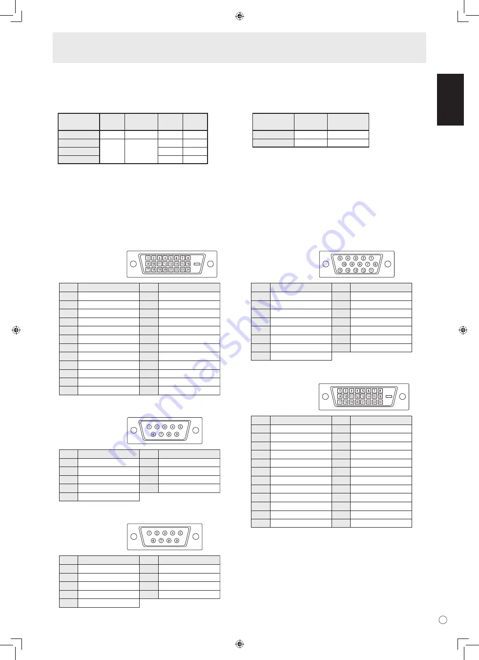
PC1/AV1 input terminal pins

(DVI-D24 pin)


No.

1
2
3
4
5
6
7
8
9

10
11
12

Function

TMDS data 2-
TMDS data 2+
TMDS data 2/4 shield
N.C.
N.C.
DDC clock
DDC data
N.C.
TMDS data 1-
TMDS data 1+
TMDS data 1/3 shield
N.C.

No.

13
14
15
16
17
18
19
20
21
22
23
24

Function

N.C.
+5 V
GND
Hot-plug detection
TMDS data 0-
TMDS data 0+
TMDS data 0/5 shield
N.C.
N.C.
TMDS clock shield
TMDS clock+
TMDS clock-

RS-232C input terminal pins

(D-sub 9 pin)


No.

1
2
3
4
5

Function

N.C.
Transmitted data
Received data
N.C.
GND

No.

6
7
8
9

Function

N.C.
N.C.
N.C.
N.C.

RS-232C output terminal pins

(D-sub 9 pin)


No.

1
2
3
4
5

Function

N.C.
Received data
Transmitted data
N.C.
GND

No.

6
7
8
9

Function

N.C.
N.C.
N.C.
N.C.

PC2 input terminal pins

(Mini D-sub 15 pin)


No.

1
2
3
4
5
6
7
8

Function

Red video signal input
Green video signal input
Blue video signal input
N.C.
GND
GND for red video signal
GND for green video signal
GND for blue video signal

No.

9

10
11
12
13
14
15

Function

+5 V
GND
N.C.
DDC data
Hsync signal input
Vsync signal input
DDC clock

PC/AV output terminal pins

(DVI-D24 pin)


No.

1
2
3
4
5
6
7
8
9

10
11
12

Function

TMDS data 2-
TMDS data 2+
TMDS data 2/4 shield
N.C.
N.C.
DDC clock
DDC data
N.C.
TMDS data 1-
TMDS data 1+
TMDS data 1/3 shield
N.C.

No.

13
14
15
16
17
18
19
20
21
22
23
24

Function

N.C.
+5 V
GND
Hot-plug detection
TMDS data 0-
TMDS data 0+
TMDS data 0/5 shield
N.C.
N.C.
TMDS clock shield
TMDS clock+
TMDS clock-

Power management

This monitor conforms to VESA DPMS and DVI DMPM. Both your video card and computer must support the same standard in 

order for the monitor’s power management function to work.

DPMS

ON STATE

STANDBY

SUSPEND

OFF STATE

Screen

Display

No 

display

Power

consumption

325 W

7.5 W*

Hsync

Yes

No

Yes

No

Vsync

Yes
Yes

No
No

DMPM

Monitor ON

Active OFF

Screen

Display

No display

Power 

consumption

325 W

7.5 W*

DPMS: Display Power Management Signaling

DMPM: Digital Monitor Power Management

* When AUTO INPUT CHANGE is OFF. 11.5 W when it is 

ON.

DDC (plug and play)

The monitor supports the VESA DDC (Display Data Channel) standard.

DDC is a signal standard for plug and play between monitors and computers. Information about resolution and other parameters 

is exchanged between the two. This function can be used if the computer supports DDC and it has been configured to detect 

plug-and-play monitors.

There are several types of DDC, depending on the communication method used. This monitor supports DDC2B.

Summary of Contents for GD-F52L1

Page 1: ...DEUTSCH FRANÇAIS LCD DISPLAY MONITOR BEDIENUNGSANLEITUNG LCD DISPLAYMONITOR MANUEL D INSTRUCTIONS MONITEUR LCD INSTRUCTIONS GD F52L1 ENGLISH ...

Page 2: ...145 Friedberg Deutschland Cher e client e Cet appareil est conforme aux directives et normes européennes en vigueur concernant la compatibilité électromagnétique et à la sécurité électrique Représentant européen de la société Victor Company of Japan Limited JVC Technology Centre Europe GmbH Postfach 10 05 52 61145 Friedberg Allemagne Уважаемый клиент Данное устройство соответствует действительным ...

Page 3: ...UTION The AC outlet shall be installed near the equipment and shall be easily accessible IMPORTANT INFORMATION FOR CUSTOMERS IN U K IMPORTANT The wires in this mains lead are coloured in accordance with the following code GREEN AND YELLOW Earth BLUE Neutral BROWN Live As the colours of the wires in the mains lead of this apparatus may not correspond with the coloured markings identifying the termi...

Page 4: ... waste disposal service or the shop where you purchased the product Penalties may be applicable for incorrect disposal of this waste in accordance with national legislation Business users If you wish to dispose of this product please visit our web page www jvc europe com to obtain information about the take back of the product Other Countries outside the European Union If you wish to dispose of th...

Page 5: ... similar surface since they can block ventilation openings Do not place the product in an enclosed place such as a bookcase or rack unless proper ventilation is provided or the manufacturer s instructions are followed 9 Power cord protection The power cords must be routed properly to prevent people from stepping on them or objects from resting on them 10 The LCD panel used in this product is made ...

Page 6: ...he specified batteries only Install the batteries with due attention to the plus and minus sides of the batteries according to the instructions in the compartment Do not mix old and new batteries Do not mix batteries of different types Voltage specifications of batteries of the same shape may vary Replace an exhausted battery with a new one promptly If you will not use the remote control for a long ...

Page 7: ...quipment or in places where there is likelihood of high temperature as this may lead to generation of excessive heat and outbreak of fire The Power Cord Do not damage the power cord nor place heavy objects on it stretch it or over bend it Also do not add extension cords Damage to the cord may result in fire or electric shock Use only the power cord supplied with the monitor Insert the power plug dir...

Page 8: ... Cord 12 Mounting the Temporary Stands 12 Binding Cables 13 Preparing the Remote Control Unit 13 Installing the batteries 13 Remote control operation range 13 Basic Operation Turning Power On Off 14 Turning on the main power 14 Turning power on off 14 Disabling power on off operations 14 Basic Operation 15 Menu Items 17 Displaying the menu screen 17 Menu item details 18 Adjustments for PC screen d...

Page 9: ...lace a blank sticker onto the JVC logo to cover the logo Vertical logo sticker 2 For environmental protection Do not dispose of batteries in household waste Follow the disposal instructions for your area Part Names Front view INPUT 1 2 3 4 5 1 LCD panel 2 Remote control sensor See page 13 3 Input switch See page 15 4 Power switch See page 14 5 Power LED See page 14 TIPS Use a pointed object such a...

Page 10: ... 10 9 RS 232C output terminal D sub 9 pin See page 24 10 RS 232C input terminal D sub 9 pin See page 24 11 External speaker terminals See page 11 12 PC AV audio output terminals See page 11 13 AV audio input terminals See page 10 14 PC audio input terminal See page 10 15 Handles 16 Vents Remote control unit 1 2 3 4 5 6 9 8 7 1 Signal transmitter 2 POWER button See page 14 3 MUTE button See page 15...

Page 11: ...e that heat emitted from the monitor may discolour or alter the wall If it is difficult to provide such space because the monitor is installed inside a housing or for other reasons take other measures to keep the ambient temperature between 0 C and 40 C such as installing a fan in the housing Adhere to the following when installing the monitor in the vertical orientation Failing to adhere to the f...

Page 12: ... graphics board to verify that input signals conform to specifications of this monitor Hsync 66 3 kHz Vsync 60 Hz and Dot frequency 148 5 MHz See page 34 If there is a check box to disable EDID in display control panel check it when using PC3 BNC Use the automatic screen adjustment when a PC screen is displayed for the first time using PC2 or PC3 or when the setting of the PC is changed See page 22 ...

Page 13: ...mpatible RS 232C input output terminals You can control the monitor from a PC by connecting a commercially available RS 232 straight cable between this terminal and the PC See page 24 Connecting external speakers Be sure to use external speakers with an impedance of 6 Ω and a rated input of at least 7 W 1 2 1 While pushing the tab insert the tip of the cable 2 Release the tab TIPS Be sure to conne...

Page 14: ...om the monitor and mount the temporary stand using the screws Temporary stand Screws Caution After detaching the temporary stand be sure to re mount the removed screws on the monitor Mounting the Temporary Stands Caution Do not use a power cord other than the one supplied with the monitor 1 Turn off the main power switch 2 Plug the power cord supplied into the AC input terminal 3 Plug the power co...

Page 15: ...Objects between the remote control unit and the remote control sensor may prevent proper operation Replace the batteries when they run low as this may shorten the remote control s operation range If a fluorescent light is illuminated near the remote control unit it may interfere with proper operation Do not use it with the remote control of other equipment such as air conditioner stereo components ...

Page 16: ...ternately in red and orange in standby mode Date time setting If the time has yet to be set when the monitor is first turned on the date time setting screen appears Set the date and time DATE TIME SETTING SET CANCEL 07 OK MENU 20 01 01 00 00 1 Press or to select the date and time and press or to change the numerical values 2 Select SET and then press MENU Be sure to set the date and time The date t...

Page 17: ...ttons for about 4 seconds the VOLUME menu automatically disappears 5 BRIGHT Backlight adjustment Pressing or displays the BRIGHT menu when the menu screen is not displayed B R I G H T 15 Press or to adjust the brightness If you do not press any buttons for about 4 seconds the BRIGHT menu automatically disappears 6 SIZE Screen size selection The menu is displayed Press or to select the screen size ...

Page 18: ...itor s screen size switching or dual screen display functions to compress or expand the screen for commercial or public viewing in establishments like cafes or hotels may infringe on the rights of the creators as protected by Copyright Law so please be careful When Enlarge is set the screen size is fixed to WIDE mode When dual screen display is selected the screen size cannot be changed The appeara...

Page 19: ... 48 4 kHz 4 Press or to adjust the setting AUTO CONTRAST BLACK LEVEL SHARPNESS 40 96 12 PC2 ANALOG 1 2 PICTURE SCREEN PICTURE AUDIO SETUP OPTION ENLARGE PIP PbyP OK MENU 1 0 2 4 x 7 6 8 V 60 Hz H 48 4 kHz For items that have press make settings and then press MENU 5 Press MENU twice to close the menu screen TIPS The menu will differ depending on the input mode The menu screen will close automatica...

Page 20: ...wards green and selecting changes it towards magenta COLORS AV input Adjusts the colour intensity SHARPNESS Adjusts the sharpness of the image ADVANCED AV input You can adjust more specifically See page 22 COLOR MODE Changes the colour mode on the screen The colour mode on the screen can also be changed using a remote control unit See page 15 sRGB is PC input only See page 15 for details WHITE BALA...

Page 21: ...ment which is connected to AV3 input terminal AUTO PAL PAL 60 SECAM NTSC3 58 NTSC4 43 When AUTO is selected the colour system is automatically set according to the input signal AUDIO OUTPUT Sets the volume of sound output from the PC AV audio output terminals VARIABLE You can adjust the volume using VOLUME FIXED Fixes the sounds 480LINES PC2 PC3 If a computer connected to the PC2 PC3 input termina...

Page 22: ...wing adjustments of ADVANCED are invalid and adjusting is disabled 3D NR MPEG NR and 3D Y C ENLARGE PC input ENLARGE MODE Sets the number of screen splits used for the enlargement See page 21 ENLARGE POS Specify the split screen to be displayed when the enlargement function is used See page 21 BEZEL H BEZEL V Sets the frame width of the display when the enlargement function is used H POS Adjust th...

Page 23: ...9 SCHEDULE No POWER DAY OF THE WEEK TIME INPUT XXXX XX XX XXX XX XX XX PC2 ANALOG 2 OK MENU 1 0 2 4 x 7 6 8 V 60 Hz H 48 4 kHz 1 3 4 5 1 Press or to select the SCHEDULE number and press 2 Set the SCHEDULE See the description below Press or to select items and press or to change the setting 3 Press MENU SCHEDULE becomes effective 1 SCHEDULE effective SCHEDULE not effective 2 POWER ON Switches the m...

Page 24: ... compression 3D Y C AV3 Specify whether to perform 3 dimension Y C separation If dot interference or cross colour is occurring in fast motion scenes selecting OFF may improve the image quality Adjustments for PC screen display Automatic adjustment When you use the PC2 input terminal or PC3 input terminals to display a PC screen for the first time or when you change the setting of the PC use the aut...

Page 25: ...ack on ADJUSTMENT LOCK You can disable operations on the monitor and the remote control unit that use buttons OFF Enables operation 1 Disables all operations other than turning power on off and FUNCTION 2 Only the FUNCTION operation is enabled Disables all operations other than FUNCTION not even power on off OSD DISPLAY Hides shows menus The FUNCTION screen cannot be hidden ON Displays the menus O...

Page 26: ...2C output terminal RS 232C input terminal Communication conditions Set the RS 232C communication settings on the PC to match the monitor s communication settings as follows Baud rate 9600 bps Stop bit 1 bit Data length 8 bits Flow control None Parity bit None Communication procedure Command format When a command is sent from the PC to the monitor the monitor operates according to the received comm...

Page 27: ...NPS ASNC WIDE EMAG EPOS PXSL POWR AGIN MWIN MWIP MWPP ESTG When control via RS 232C is locked to prevent use using the operation lock function see page 23 E C D K O L Return code 0DH 0AH Communication interval After OK or ERR is returned you must send the following commands To set a timeout for the command response specify 10 seconds or longer Provide an interval of 100 ms or more between the comm...

Page 28: ...me to 20 OK 001 The volume of the monitor with ID number 1 the one directly connected to the PC is set to 20 The IDSL command is effective only once for the immediately succeeding command IDLK The parameter of this command sets the ID number of the monitor The monitor is subject to all subsequent commands Example IDLK0002 Following commands are for the monitor with ID number 2 WAIT Searching for m...

Page 29: ...t a value has been returned by a specific set assign ID numbers to each monitor in advance When some monitors do not return their responses the probable cause is that the monitors could not receive the command or command processing is not complete Do not send a new command Example When 4 monitors are connected and assigned ID numbers 1 through 4 VOLM030 WAIT OK 001 OK 002 OK 003 OK 004 If 4 monitor...

Page 30: ...mode Yes 1 Returns from standby mode R 0 Standby mode 1 Normal mode 2 Input signal waiting mode INPUT MODE SELECTION INPS W 0 Toggle change for input mode Terminals not selected in DVI SELECT BNC SELECT cannot be selected Yes 1 PC1 DIGITAL ERR when AV DIGITAL is selected for DVI SELECT 2 PC2 ANALOG 3 AV2 COMPONENT ERR when PC ANALOG is selected for BNC SELECT 4 AV3 VIDEO 6 PC3 ANALOG ERR when AV C...

Page 31: ...O menu Function Command Direction Parameter Reply Control Response contents TREBLE AUTR WR 10 10 10 10 Yes BASS AUBS WR 10 10 10 10 BALANCE AUBL WR 10 10 10 10 RESET ARST W 3 No SETUP menu Function Command Direction Parameter Reply Control Response contents MONITOR STDR WR 0 1 0 1 0 LANDSCAPE 1 PORTRAIT Yes LANGUAGE LANG WR 14 14 ENGLISH Yes 1 1 DEUTSCH 2 2 FRANÇAIS 3 3 ITALIANO 4 4 ESPAÑOL 5 5 РУ...

Page 32: ...nput mode is PC Function Command Direction Parameter Reply Control Response contents ENLARGE MODE EMAG WR 0 4 0 4 0 OFF 1 2 x 2 2 3 x 3 3 4 x 4 4 5 x 5 No BEZEL WIDTH WIDTH OF THE SHORTER SIDE BEZH WR 0 100 0 100 WIDTH OF THE LONGER SIDE BEZV WR 0 100 0 100 IMAGE POSITION 2 x 2 EPOS WR 0 3 0 3 See page 21 IMAGE POSITION 3 x 3 EPOS WR 0 8 0 8 IMAGE POSITION 4 x 4 EPOS WR 0 15 0 15 IMAGE POSITION 5 ...

Page 33: ...R Value Yes SERIAL NO SRNO R Value BRIGHT VLMP WR 0 31 0 31 Brightness Yes TEMPERATURE SENSOR DSTA R 0 Internal temperature normal Yes 1 Internal temperature abnormal Standby mode 2 Internal temperature abnormal Temperature is normal now but it was abnormal during operation 3 Internal temperature abnormal Brightness of the backlight decreases 4 Temperature sensor abnormal TEMPERATURE ACQUISITION E...

Page 34: ...le with this monitor See page 34 Control buttons do not work There is no picture Some kind of load noises from outside might interfere with normal operation Turn off the power and turn it on after waiting at least 5 seconds and then check the operation The input mode changes automatically When the AUTO INPUT CHANGE is ON and no signal is present in a selected input mode the AUTO INPUT CHANGE autom...

Page 35: ...e x 1 PC Analogue Mini D sub 15 pin 3 rows x 1 BNC 1 2 x 1 Audio 3 5 mm mini stereo jack x 1 AV Composite video BNC x 1 Component BNC Y Cb Pb Cr Pr 1 x 1 Audio RCA pin L R x 1 Serial RS 232C D sub 9 pin x 1 Output terminals PC AV Digital DVI D 24 pin 3 x 1 Audio RCA pin L R x 1 Serial RS 232C D sub 9 pin x 1 Speaker 7 W 7 W 6 Ω Power requirement AC 100 V 240 V 50 60 Hz Operating temperature 0 C to...

Page 36: ...MHz 108 23 MHz 117 01 MHz 134 99 MHz 135 76 MHz Yes Yes Yes Yes Yes Yes Yes Yes Yes Yes Yes Yes Yes Yes Yes Yes Yes Yes Yes Yes Yes Yes Yes Yes Yes Yes Yes Yes Yes Yes Digital signal Yes Yes Yes Yes Yes Yes Yes Yes Yes Yes Yes Yes Yes Yes Yes Yes Yes Yes Yes Yes Yes 1 Displays a reduced image All are compliant only with non interlaced Depending on the connected PC images may not be displayed prope...

Page 37: ...ion TMDS data 2 TMDS data 2 TMDS data 2 4 shield N C N C DDC clock DDC data N C TMDS data 1 TMDS data 1 TMDS data 1 3 shield N C No 13 14 15 16 17 18 19 20 21 22 23 24 Function N C 5 V GND Hot plug detection TMDS data 0 TMDS data 0 TMDS data 0 5 shield N C N C TMDS clock shield TMDS clock TMDS clock Power management This monitor conforms to VESA DPMS and DVI DMPM Both your video card and computer ...

Page 38: ...36 E M E M O ...

Page 39: ......

Page 40: ...1007STH MW SH 2007 Victor Company of Japan Limited 07K DSC1 TINSM1118MPZZ 1 ...

Reviews: