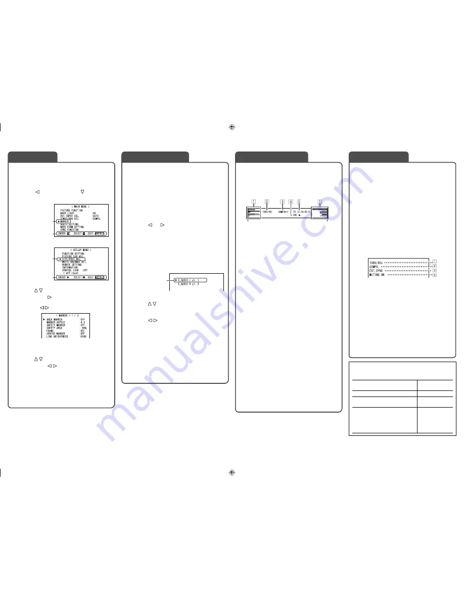
7
If you press the INPUT SELECT button of the
current input, the status of the input signal
and setting of muting are displayed for about 3
seconds.
• Make the setting to display/hide the status in
“STATUS DISPLAY” of the “INFORMATION” (
☞
page 15).
• When “STATUS DISPLAY” is set to “AUTO” or
“ON,” the status below is also displayed in the
following cases:
– When you change the input
– When the signal condition of the current input
changes
– When you turn on the monitor
• When “STATUS DISPLAY” is set to “ON,” the
signal format will remain displayed 3 seconds
after the status is displayed.
1
Signal format
• For the contents displayed, see “On the
signal format” below and “Available signals”
on page 9.
2
Signal format of DVI input or setting of
“COMPO./RGB SEL.”
☞
“DVI INPUT SEL.” or “COMPO./RGB SEL.”
on page 10
3
Displayed when “SYNC INPUT SEL.” is set
to “EXT.” (external synchronization)
☞
“ SYNC FUNCTION” on page 13
4
Setting of “MUTING”
• Displayed only when muting is activated.
☞
“
4
MUTING button” on page 6
The monitor displays the information below.
• Make the setting to display/hide each
information using the MENU with the exception
of
5
, controlled with a button.
• Select the position of the information display (
☞
“POSITION” in “INFORMATION” on page 15).
1
Audio level meter
• Not displayed when “LEVEL METER ch” is set
to “OFF.” (
☞
“AUDIO SETTING” on page 12)
2
Signal format
• Displayed when “STATUS DISPLAY” is set to
“ON.” (
☞
“INFORMATION” on page 15)
• For the contents displayed, see “On the
signal format” below and “Available signals”
on page 9.
3
Source name assigned in “CHARACTER SET.”
• Displayed when “SOURCE ID” is set to “ON.”
• Displayed in large letters when “STATUS
DISPLAY” is set to “OFF” or “AUTO.”
☞
“INFORMATION” on page 15
4
CRC error indication
• Displayed when “CRC ERROR” is set to “ON.”
(
☞
“INFORMATION” on page 15)
• A red square is displayed when an error
occurs.
5
Time code
• When the input signal includes no time code,
“TC – –:– –:– –:– –” is displayed.
☞
“
r
T.C. (time code) button/lamp” on page 6
• When any information of
1
,
2
,
3
, or
4
above is displayed while signals come in from
equipment other than a computer, the picture is
displayed without overlapping the information
display area.
However, the information display will overlap
with the picture when...
– displaying the picture with higher resolution
than the resolution of the panel in 1:1 mode.
– “SD4:3 LARGE” setting is “ON.”
(
☞
“FUNCTION SETTING” on page 14).
Select audio channels emitted from the speakers
(L/R) and the AUDIO ASSIGN (MONITOR OUT)
(OUT1(L)/OUT2(R)) terminals, when EMBEDDED
AUDIO signals come in to the E. AUDIO HD/SD
SDI terminal (IN1 or IN2) and SDI input (1 or 2) is
selected.
• You have to choose a group of selectable audio
channels before the channel selection (
☞
“E.AUDIO GROUP” in “AUDIO SETTING” on
page 12).
1
Press or button when a menu
is not displayed.
The screen for audio channel selection is
displayed.
• The screen for audio channel selection
automatically disappears in about 30
seconds after the previous operation.
2
Press buttons to select the left
(L ch) or right (R ch).
3
Press buttons to select an
audio channel.
• Each time you press the button, the audio
channel changes according to the settings of
“E.AUDIO GROUP” (
☞
“NOTE” on page 12).
4
Press MENU button.
The screen for audio channel selection
disappears.
• The setting is memorized for each input (SDI 1
and SDI 2).
1
Display the menu.
To display the MAIN MENU
\
Press MENU button.
To display the SET-UP MENU
\
Press button while holding button.
2
Press buttons to select an item,
then press button.
• For some items, adjustments will be made by
pressing .
3
Press buttons to select an item,
then press buttons to make
adjustments.
4
Press MENU button to return to the
previous menu.
• Pressing the button again finishes the menu
operation.
On the Status Display
Audio Channel Selection
MAIN MENU
SET-UP MENU
Selected item
Selected item
Operation guide
Selected item
Operation guide
Ex.: When “MARKER” in the MAIN
MENU is selected
Menu Operations
Audio channel selection screen
On the Information Display
On the signal format
The following messages appear depending on the
type of input signals and their conditions.
When a DVI-D signal protected
with HDCP is input
“
*
” (at the end of
the indication)
When no video signal comes in “NO SYNC”
When a noncompliant video
signal comes in
“Out of range”
When “COLOR SYSTEM” (
☞
“FUNCTION SETTING” on
page 14) is set to “AUTO” and
the noncompliant composite
video signals come in
“OTHERS”
DT-V24_20L3D_EN.indd 7
DT-V24_20L3D_EN.indd 7
08.5.27 5:14:55 PM
08.5.27 5:14:55 PM


