


16
Troubleshooting
Solutions to common problems related to the monitor are described here. If none of the solutions presented here
solves the problem, unplug the monitor and consult an authorized dealer or service center.
Symptom
Probable cause and corrective action
Page
No power supply
• Turn on the POWER switch or DC switch on the rear panel.
• Firmly insert the AC power plug or DC 12 V power plug.
• When using the DC 12 V power supply, charge the battery or replace
it with the one charged.
8
8
8
No picture with the
power on
• Select the correct input with INPUT SELECT buttons.
• Connect the signal cable firmly.
• Turn on the power of the connected component and set the output
correctly.
• Check if the input signal format is acceptable on the monitor.
6
8
—
9
No sound
• Adjust the volume level.
• Deactivate the muting function.
• Connect the signal cable firmly.
• Turn on the power of the connected component and set the output
correctly.
6
6
8
—
“OTHERS” or “Out of
range” appears.
• Check if the input signal format is acceptable on the monitor.
7, 9
“NO SYNC” appears.
• Select the correct input with INPUT SELECT buttons.
• Connect the signal cable firmly.
• Turn on the power of the connected component and output video
signals. Or, check if the video output of the component (video output
setting of the VCR or graphic board of the computer) is set correctly.
6
8
—
Wrong color, no color
• Adjust the each picture adjustment knob on the front panel or adjust
the items of “PICTURE SUB ADJ.” in the SET-UP MENU. Or, perform
“reset” in “PICTURE SUB ADJ.”
• Check if the setting of COLOR OFF or SCREENS CHECK buttons
are appropriate.
• Select the proper color system (“COLOR SYSTEM”) in “FUNCTION
SETTING” of the SET-UP MENU.
• Adjust the items of “WHITE BALANCE SET.” in the SET-UP MENU.
Or, perform “reset” in “WHITE BALANCE SET.”
6, 12
6
12
12
The picture becomes
blurred.
• Adjust the picture contrast or brightness by using the adjustment
knobs on the front panel. Or, adjust “CONTRAST” or “BRIGHT” of
“PICTURE SUB ADJ.” in the SET-UP MENU.
6, 12
Wrong picture position,
wrong picture size.
• Check if the setting of 1:1 or ASPECT buttons is appropriate.
• Check if the input signal format is acceptable on the monitor.
• Adjust the picture size (H SIZE/V SIZE) or position (H POSITION/V
POSITION) of “SIZE/POSI. ADJ.” in the SET-UP MENU.
• For some signals, the picture cannot be displayed fully in the effective
screen area. There is no sure method to solve this problem.
6
9
12
—
Some items do not
appear on the menu.
• The items which are not available for the current input or the current
input signal are not displayed on the menu. Change the input or the
input signal.
• The items controlled by the MAKE system do not appear on the
menu.
—
14
Buttons on the monitor
do not work.
• Set “CONTROL LOCK” in the SET-UP MENU to “OFF.”
13
The following are not malfunctions.
• When a still image is displayed for a long time, it may remain indistinctly on the screen after the picture has
changed. Though the remaining picture will disappear after a while, there may be a case that it remains
for a long period depending on the length of time the still image was displayed for. This is due to the
characteristics of the LCD display and is not a malfunction.
• The red spots, blue spots and green spots on the panel surface are a normal characteristic of LCD displays,
and not a problem. The LCD display is built with very high precision technology; however, be aware that a
few pixels may be missing or constantly lit.
• The following symptoms are problems only when pictures or sounds are not played back normally.
– A slight electric shock occurs when you touch the monitor.
– The top and/or rear panel of the monitor becomes hot.
– The monitor emits a cracking noise.
– The monitor emits a mechanical noise.
7
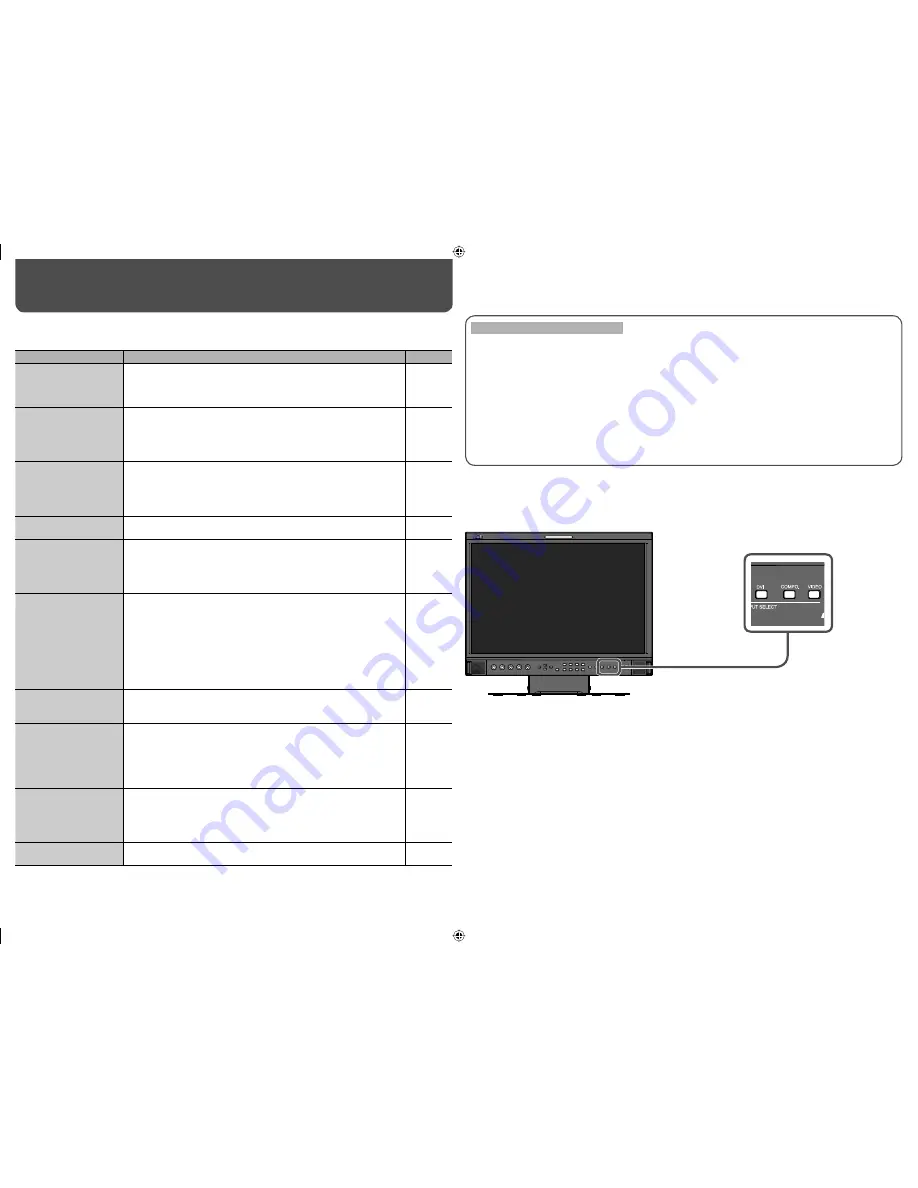
Self-check program
This monitor has a self-check function, which allows it to detect malfunctions and alert you. This makes
troubleshooting easier. Whenever a problem occurs, one or some of the INPUT SELECT lamps will flash. If this
happens, follow the steps below and contact your dealer to resolve the problem.
When the screen goes blank, and one or some of the INPUT SELECT lamps (DVI/COMPO. /VIDEO) on the
front control panel start flashing...
1
Check which lamps are flashing.
2
Turn off the POWER switch or DC switch on the rear panel.
3
When AC power supply is used, disconnect the AC power cord from the AC outlet.
When DC 12 V power supply is used, detach the battery or disconnect the plug
from the DC IN 12V terminal.
4
Contact your dealer with the information about which lamps are flashing.
• If you turn on the monitor soon after turning it off (or after a short-term power failure), the INPUT SELECT
lamps may flash and no image may be displayed.
When this happens, turn off power and wait at least 10 seconds before turning on the monitor again. If the
INPUT SELECT lamps do not flash, you can use the monitor as normal.
DT-V17L2D_EA_EN_R.indd 16
DT-V17L2D_EA_EN_R.indd 16
07.9.14 7:01:52 PM
07.9.14 7:01:52 PM