background image

10

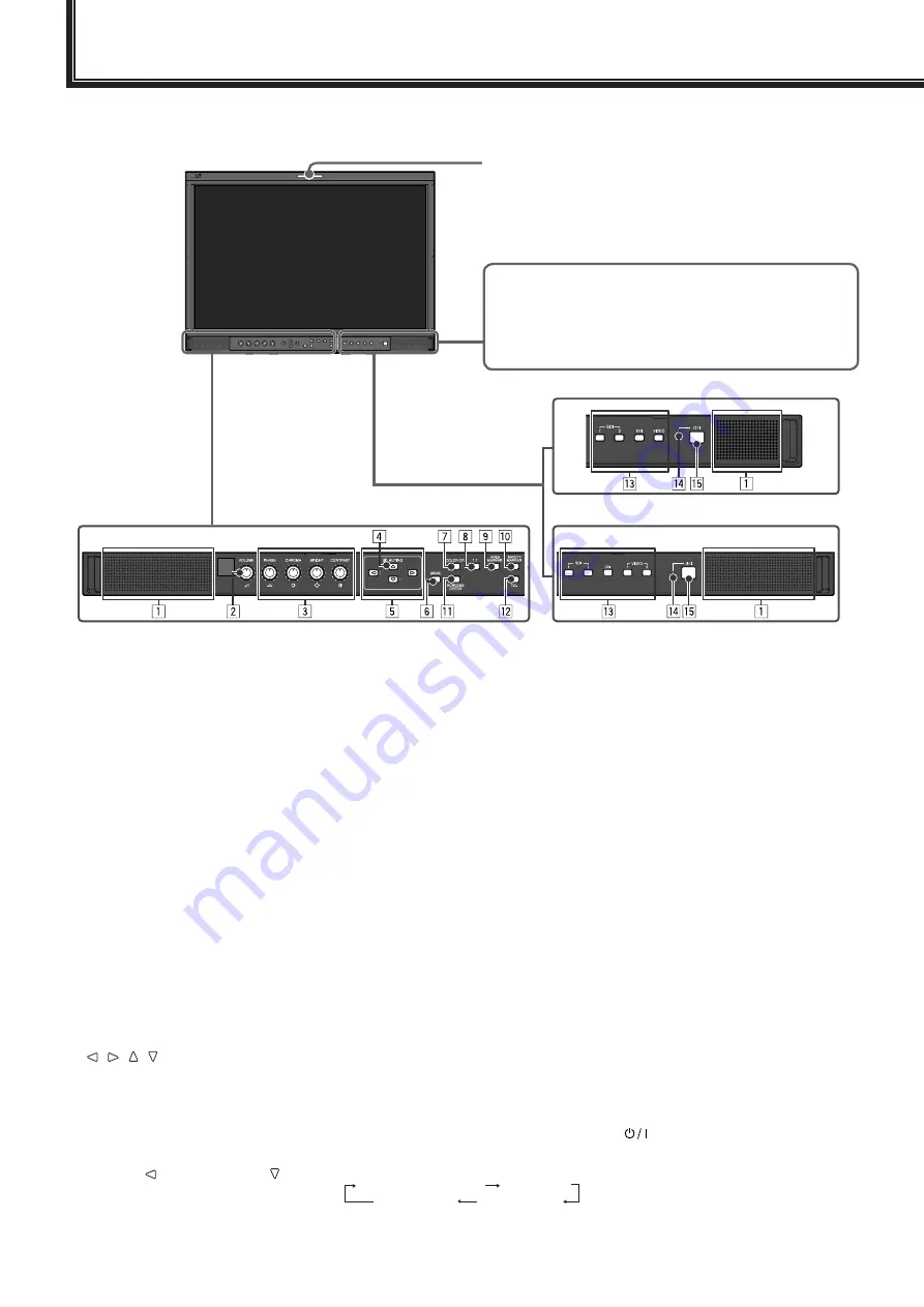
Front panel

1

  Speakers (stereo)

The speakers emit the same audio 

signal emitted from the AUDIO ASSIGN 

(DT-R24L4D) / AUDIO (DT-R17L4D) 

(MONITOR OUT) terminals. (

 “ 

6


AUDIO ASSIGN (DT-R24L4D) / AUDIO 

(DT-R17L4D) (MONITOR OUT) terminals” 

on page 9)

2

  VOLUME adjustment knob

Adjusts the volume.

3

  Picture adjustment knob

PHASE:

 Adjusts the picture hue.

CHROMA:

 Adjusts the picture color density.

BRIGHT:

 Adjusts the picture brightness.

CONTRAST:

 Adjusts the picture contrast.

PHASE and CHROMA cannot be 

adjusted for certain signal formats.

When “COMPONENT PHASE” is set to 

“DISABLE” and an NTSC signal is input, 

PHASE can be adjusted (

 page 15).

4

  MUTING button

Turns off the sound when no menu screen 

is displayed.

To cancel the function, press the button 

again or turn the VOLUME adjustment knob.

Muting function is also canceled when 

“BALANCE” of “AUDIO SETTING” in the 

MAIN MENU is changed (

 page 14).

5

     /   /   /   buttons

When a menu screen is displayed

Selects or adjusts menu items. (

 “The 

operation procedure” on page 12)

When no menu screen is displayed

Selects the audio channels of 

EMBEDDED AUDIO signals. (

 “Audio 

Channel Selection” on page 11)

Pressing   button while holding   button 

displays the SET-UP MENU. (

 “The 

operation procedure” on page 12)

6

  MENU button

Activates/deactivates the display of 

the MAIN MENU. (

 “The operation 

procedure” on page 12)

7

  COLOR OFF button/lamp

Displays only the luminance signal.

This function does not work for RGB 

input signals.

8

  1:1 button/lamp

Displays the picture in the original 

resolution of the input signal.

The aspect ratio of the picture may 

change depending on the input signal.

9

  AREA MARKER button/lamp

Displays/hides the area marker.

Select the style of the area marker 

in “MARKER” of the MAIN MENU 

(

 page 13).

This function works only when displaying 

the picture in 16:9 aspect ratio.

This function does not work when 

“AREA MARKER” or “R-AREA 

MARKER” is set to “OFF” in “MARKER.”

p

  SAFETY MARKER button/lamp

Displays/hides the safety marker.

Adjust the area of the safety marker in 

“MARKER” of MAIN MENU (

 page 13).

This function does not work when 

displaying the picture in the 1:1 mode.

This function does not work when 

“SAFETY MARKER” or “R-SAFETY 

MARKER” is set to “OFF” in “MARKER.”

q

  SCREENS CHECK button/lamp

Displays only the selected element (R, G, 

or B) of the video signal.

Each time you press this button, the 

picture changes in the following order.

RGB (Normal screen)

Red screen

Blue screen

Green screen

w

  T.C. (time code) button/lamp

Activates/deactivates the display of the time 

data (time code) contained in the SDI signal. 

(

 “On the Information Display” on page 11)

Select the time code type in 

“INFORMATION” of SET-UP MENU (


page 17).

e

  INPUT SELECT buttons/lamps

Selects an input.

SDI 1:


 E. AUDIO HD/SD SDI (IN 1) 

terminal

SDI 2:


 E. AUDIO HD/SD SDI (IN 2) 

terminal

DVI:


DVI-D (HDCP) terminal

DT-R24L4D

VIDEO 1:

 VIDEO (INPUT 1) terminal

VIDEO 2:

 VIDEO (INPUT 2) terminal

DT-R17L4D

VIDEO:

  VIDEO terminal

The lamp for the selected input lights.

r

  Power lamp

Unlit:


 The monitor is completely off 

(the power switch on the rear 

panel is turned off).

Lights in Green:


The monitor is on.

Lights in orange:


The monitor is off (on standby).

Flashes in orange:


 The monitor is in the P. SAVE 

(power save) mode. (

 “NO 

SYNC ACTION” in “SYNC 

FUNCTION” on page 15)

t


 button

Turns on and off (on standby) the monitor.

The power switch is equipped on the rear 

panel of the monitor (


1

 on page 8).

Tally lamp

This lamp is controlled by the tally function of the MAKE/TRIGGER 

terminal.

You can select the color of the tally lamp from “GREEN” or “RED.”  

(

 “TALLY SELECT” in “FUNCTION SETTING” on page 15 and 

“External Control” on page 18)

“NO EFFECT” is displayed when you press a button which is 

not available for the current input or signal format (the lamp 

lights even when the function does not actually work).

The items controlled by the MAKE system cannot be controlled 

by the buttons on the front panel (“REMOTE ON” is displayed 

and the lamps do not light).

The illustration of the 

monitor is of DT-R24L4D.

Daily Operations

DT-R24L4D

DT-R17L4D

Summary of Contents for DT-R17L4D

Page 1: ... FORMAT LCD MONITOR MULTI FORMAT LCD MONITOR MONITEUR LCD MULTI FORMAT MONITOR LCD MULTIFORMATO MONITOR LCD MULTIFORMATO МУЛЬТИФОРМАТНЫЙ ЖК МОНИТОР INSTRUCTIONS BEDIENUNGSANLEITUNG MANUEL D INSTRUCTIONS ISTRUZIONI MANUAL DE INSTRUCCIONES ИHCТРУKЦИЯ ПО ЭКСПЛУАТАЦИИ ...

Page 2: ...NOT OPEN The lightning flash with arrowhead symbol within an equilateral triangle is intended to alert the user to the presence of uninsulated dangerous voltage within the product s enclosure that may be of sufficient magnitude to constitute a risk of electric shock to persons The exclamation point within an equilateral triangle is intended to alert the user to the presence of important operating ...

Page 3: ...Rear panel 8 Daily Operations 10 Front panel 10 Menu Configuration 12 The operation procedure 12 Menu Transition Diagram 12 MAIN MENU 13 SET UP MENU 15 External Control 18 About the external control 18 Using the MAKE TRIGGER system 18 Using the serial communication 20 Troubleshooting 22 Self check program 23 Specifications 24 General 24 LCD panel 24 Input output terminals 24 Dimensions 25 Availabl...

Page 4: ...ure the service technician has used replacement parts specified by the manufacturer or equivalents Unauthorized substitutions may result in fire electric shock or other hazards Upon completion of any service or repairs to this product ask the service technician to perform safety checks to determine that the product is in proper operating condition Under the following conditions 1 Turn off the powe...

Page 5: ...nstructions 3 Heed all warnings 4 Follow all instructions 5 Do not use this apparatus near water 6 Clean only with dry cloth 7 Do not block any ventilation openings Install in accordance with the manufacturer s instructions 8 Do not install near any heat sources such as radiators heat registers stoves or other apparatus including amplifiers that produce heat 9 Do not defeat the safety purpose of t...

Page 6: ...pair cable A straight LAN cable 2 0 m REMOTE cable twist pair cable A straight LAN cable 2 0 m Inrush current of the apparatus DT R17L4D 14 80 ampere DT R24L4D 15 44 ampere CAUTION In case where the strong electromagnetic waves or magnetism are near the audio cable or the signal cable the sound or the picture will contain noise In such cases please keep the cable away from the sources of the distu...

Page 7: ...t the screw holes on the stand support align with right and left screw holes C and E on the bottom plate tighten the two stand screws on one side four screws on both sides and finally retighten the temporarily set screws to lock the stand support and the bottom plate Screw hole C and E 5 Use no less than two commercially available screws no less than four screws on both sides for the screw holes 1...

Page 8: ...ich can adequately withstand earthquakes conceivable vibrations and other external forces Mounting On Wooden Walls The weight of the unit should be borne by the wall posts or studs and these should be reinforced if insufficiently strong Do not install the Wall Mounting Unit on walls made of plasterboard or thin plywood Use the commercially sold screws best suited for the wall structure and materia...

Page 9: ... 4 For DT R24L4D VIDEO INPUT 1 INPUT 2 terminals BNC For DT R17L4D VIDEO terminals BNC Input IN and output OUT terminals for the composite signals 5 For DT R24L4D AUDIO ASSIGN IN 1 IN 2 terminals pin jack For DT R17L4D AUDIO IN terminals pin jack Input terminals for the analog audio signals Use this terminal for the analog audio connection of the SDI When a superimposed signal EMBEDDED AUDIO signa...

Page 10: ...f 48 kHz 8 E AUDIO HD SD SDI SWITCHED OUT terminal BNC Output terminal for the HD SD SDI signals The SDI signals of the current input SDI 1 or SDI 2 are re clocked then emitted When an input other than SDI 1 and SDI 2 is selected the SDI signal of the input selected last time is emitted from this terminal The signals are emitted from this terminal only when the monitor is on or in P SAVE power sav...

Page 11: ...MARKER button lamp Displays hides the safety marker Adjust the area of the safety marker in MARKER of MAIN MENU page 13 This function does not work when displaying the picture in the 1 1 mode This function does not work when SAFETY MARKER or R SAFETY MARKER is set to OFF in MARKER q SCREENS CHECK button lamp Displays only the selected element R G or B of the video signal Each time you press this b...

Page 12: ...o OFF or AUTO INFORMATION on page 17 4 CRC error indication Displayed when CRC ERROR is set to ON INFORMATION on page 17 A red square is displayed when an error occurs 5 Time code When the input signal includes no time code TC is displayed w on page 10 When any information of 1 2 3 or 4 above is displayed while signals come in from equipment other than a computer the picture is displayed without o...

Page 13: ...TO ASPECT AUDIO1 ASSIGN 1 LEVEL METER SETTING LEVEL METER CH BAR TYPE REFERENCE LEVEL OVER LEVEL BAR BRIGHTNESS PEAK HOLD E AUDIO GROUP AUDIO2 ASSIGN 1 MARKER AUDIO SETTING SYNC FUNCTION MANUAL ASPECT SD4 3 SIZE FUNCTION SETTING sub menu POSI COLOR SYSTEM PICTURE SUB ADJ CONTRAST TALLY SELECT BRIGHT DIMMER SIZE POSI ADJ H SIZE CHROMA COMPONENT PHASE H POSITION PHASE WHITE BALANCE SET V SIZE NTSC S...

Page 14: ... 2 Item To do Setting value AREA MARKER 3 Activate deactivate the area marker and select the style of it The setting values and features are as follows OFF Deactivate the marker LINE Displays the area with an outline HALF The area outside the specified aspect ratio of the screen is displayed at 50 transparency HALF L The area of the specified aspect ratio of the screen is indicated by an outline a...

Page 15: ...up of the EMBEDDED AUDIO signals The setting values and selectable audio channels of EMBEDDED AUDIO signals are as follows G means GROUP 1G channel s 1 2 3 4 1 2 3 4 1 4 1G 2G channel s 5 6 7 8 5 6 7 8 5 8 2G 1 2G channel s 1 2 3 4 5 6 7 8 1 2 3 4 5 6 7 8 1 4 1G 5 8 2G 1 8 1G 2G 3G channel s 9 10 11 12 9 10 11 12 9 12 3G 1 3G channel s 1 2 3 4 5 6 7 8 9 10 11 12 1 2 3 4 5 6 7 8 9 10 11 12 1 4 1G 5...

Page 16: ...n The adjustment bar is not displayed for some items LOWER1 UPPER1 LOWER2 UPPER2 COLOR SYSTEM Select the color system If the picture is unstable with AUTO select NTSC or PAL AUTO NTSC PAL TALLY SELECT Select the color of the tally lamp GREEN RED DIMMER Select the intensity of the button lamps NORMAL DARK COMPONENT PHASE Deactivates the function of PHASE adjustment Picture adjustment knob and PICTU...

Page 17: ...ades R CUT OFF G CUT OFF B CUT OFF 2 Adjust the cutoff point of each color red green and blue MIN 000 MAX in 256 grades sub menu Display the sub menu which enables you to adjust the items in WHITE BALANCE SET while viewing the actual picture reset Restore the default settings for the drive levels and cutoff points of the selected color temperature 2 Memorized for each color temperature REMOTE SETT...

Page 18: ...DI signal is displayed on the screen On the Information Display on page 11 OFF ON SUB HOUR METER Display the hours of use unit hour You can reset this item MODEL Display the model name of the monitor VERSION Display the version of the monitor HOUR METER Display the total hours of use unit hour This item is used for maintenance of the monitor You cannot reset this item 1 Memorized for each input 2 ...

Page 19: ...e right 2 The controller is not commercially available Consult your dealer if you need it Serial communication PC etc RS 485 IN or RS 232C RS 485 OUT RS 485 IN RS 485 OUT RS 485 IN RS 485 OUT For the details see page 20 Using the MAKE TRIGGER system The MAKE TRIGGER terminal is configured as follows You can assign a function to each pin terminal in REMOTE SETTING PIN1 PIN2 PIN3 PIN4 PIN5 in PARALL...

Page 20: ...ems or R items MARKER on page 13 to 14 4 Displays the information shown when INPUT SELECT button of the current input is pressed On the Status Display on page 11 While controlling with the MAKE system the information is displayed only at the moment of short circuiting 5 While controlling with the MAKE system the level meter is switched between displayed short circuiting and hidden opening When LEV...

Page 21: ...minal 6 RXD RXD 7 NC NC 8 GND GND Specifications of the RS 232C terminal Pin No Signal 1 NC 2 RXD 3 TXD 4 NC 5 GND This is a female terminal 6 NC 7 RTS 8 CTS 9 NC The 7th terminal and the 8th terminal are connected Command outline All commands consist of the following segments Header Monitor ID Command ID Function Data Cr 0Dh On Header Operation commands from the personal computer etc Basic comman...

Page 22: ...ta 14 1 B P W 0 Cr Turns off the monitor on standby No data 15 1 B I N A Cr Selects SDI 1 input No data 16 1 B I N B Cr Selects SDI 2 input No data 17 1 B I N C Cr Selects DVI input No data 18 1 B I N E Cr Selects VIDEO 1 DT R24L4D VIDEO DT R17L4D input No data 19 1 B I N F Cr Selects VIDEO 2 input 3 No data 20 1 B D I S P Cr Displays the status 4 No data 21 1 B A M U T E x x 2 Cr Turns muting on ...

Page 23: ...the adjustment knobs on the front panel Or adjust CONTRAST or BRIGHT of PICTURE SUB ADJ in the SET UP MENU 10 15 Wrong picture position wrong picture size Check whether the setting of 1 1 is appropriate Check AUTO ASPECT MANUAL ASPECT and SD4 3 SIZE settings in MAIN MENU Check whether the input signal format is acceptable on the monitor Adjust the picture size H SIZE V SIZE or position H POSITION ...

Page 24: ...VIDEO2 For DT R17L4D SDI 2 DVI VIDEO on the front control panel start flashing 1 Check which lamps are flashing 2 Press button to turn off on standby the monitor 3 Turn off the power switch on the rear panel 4 Disconnect the AC power cord from the AC outlet 5 Contact your dealer with the information about which lamps were flashing If you turn on the monitor soon after turning it off or after a sho...

Page 25: ...wide active matrix TFT Effective screen size Width 518 4 mm 20 1 2 Height 324 mm 12 7 8 Width 372 9 mm 14 3 4 Height 209 7 mm 8 3 8 Number of pixels displayed 1 920 x 1 200 1 366 x 768 Number of colors displayed 16 77 million Viewing angle TYP 178 Horizontally 178 Vertically 178 Horizontally 178 Vertically Brightness TYP 400 cd m2 350 cd m2 Contrast ratio TYP 1000 1 900 1 Input output terminals Mo...

Page 26: ... 3 5 8 179 7 1 8 23 5 1 160 6 3 8 215 8 1 2 67 2 3 4 60 2 3 8 6 φ8 15 5 8 70 2 7 8 70 2 7 8 64 5 2 5 8 88 2 3 1 2 DT R17L4D Front view Side view Rear view 430 17 309 12 1 4 314 1 12 3 8 300 11 7 8 18 3 4 102 4 1 8 56 2 1 4 1 3 1 16 181 7 1 4 3 1 8 100 VESA mounting holes Size M4 depth 10 mm 100 115 4 5 8 To install the monitor on a shelf To install the monitor on a wall Top view Side view Rear vie...

Page 27: ...0 30p 17 720 29 97p 720 29 97p 18 720 25p 720 25p 19 720 24p 720 24p 20 720 23 98p 720 23 98p 21 1080 60i 1080 60i 22 1080 59 94i 1080 59 94i 23 1035 60i 1035 60i 2 24 1035 59 94i 1035 59 94i 3 25 1080 50i 1080 50i 26 1080 60p 1080 60p 27 1080 59 94p 1080 59 94p 28 1080 50p 1080 50p 29 1080 30p 1080 30p 30 1080 29 97p 1080 29 97p 31 1080 25p 1080 25p 32 1080 24p 1080 24p 33 1080 23 98p 1080 23 98p...

Page 28: ...ncy computer signal on page 24 When a preset signal comes in the signal format is shown on the status display For other signals the resolution is shown Specification of the DVI D HDCP terminal Connect it to the DVI D output terminal on a personal computer Pin No Input signal Pin No Input signal Pin No Input signal 1 T M D S Data 2 9 T M D S Data 1 17 T M D S Data 0 2 T M D S Data 2 10 T M D S Data...

Page 29: ......

Page 30: ... 2010 Victor Company of Japan Limited 0610SKH CR MT ...

Reviews: