background image

(No.YD089)1-13

5.2

Displaying SYSTEM INFO

In the SYSTEM INFO there is information including Firmware Versions of the main body and the drive unit.

(1) Set the main body to JIG mode.
(2) Transmit "43-8B" to the main body by using JIG remote control unit.(Please end a setting menu pushing “SET UP” button of the

remote control unit appended to the commodity beforehand when a setting menu is displayed.)

(3) SYSTEM INFO menu is displayed in the television screen.
(4) To move cursor in SYSTEM INFO, use the "

", "

", "

", and "

" buttons of a main body or remote control unit attached to

product.

NOTE :

Items other than the ones described above are not used in service work.

(5) To quit the SYSTEM INFO menu, transmit "43-8B" to the main body by using JIG remote control unit.
(6) Cancel JIG mode.

5.2.1 Displaying the firmware version of the main body in the user mode

The version information of the main body firmware can be displayed in the normal mode (user mode) without using the Jig mode.
The version can be checked by the user operation when it is required to check the version when there are failure inquiries from the
users.

(1) Turn the power of the main body ON.
(2) Press the “SET UP” button of the supplied remote control unit to display the setting menu screen.
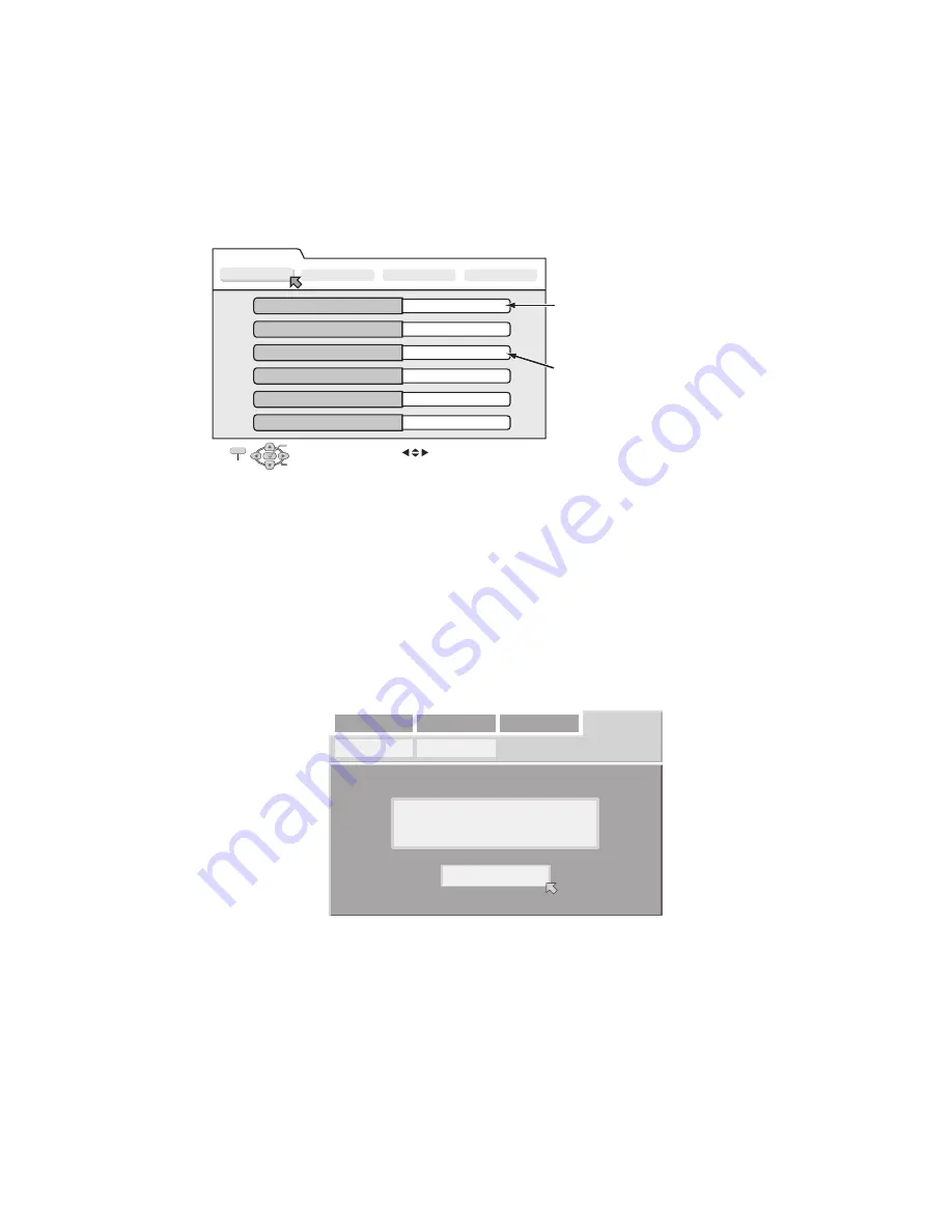
(3) Move the arrow to the “INITIAL SET UP” tab, keep pressing the “STOP” button of the main body for 10 seconds in that condition.
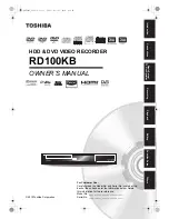
(4) The screen changes to the display shown in the below diagram, and the firmware version of the main body is indicated.
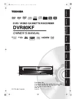
S y s t e m   I n f o

Version Info 1

Version Info 2

NAVI Info

Initialize

Application Software Version

0 . 5 8

Boot Loader Software Version

1 . 2 / 2 7 6

DVD Drive Firmware Version

P 0 2 0

Regiaon

2

CPRM Key DownLoad

D o n e

HDMI CPU Version

1 6

OK

SELECT

SELECT WITH [             ] THEN PRESS [ENTER]
PRESS [ "8b" ] TO EXIT

EXIT

The example of a display 

< Version Info 1 >

Firmware version of the main body.
When the firmware of the main body is updated,
this part is changed.

Firmware version of the drive unit.
When the firmware of the main body is updated,
this part is changed.

INITIAL SET UP

VERSION : 0.58

O  K

TUNER SET

CLOCK SET

DVD VIDEO SET UP HDD/DVD SET UP FUNCTION SET UP

Summary of Contents for DR-MH300BE

Page 1: ...ISASSEMBLY 1 7 4 ADJUSTMENT 1 10 5 TROUBLESHOOTING 1 11 Since the whole mechanism assembly unit is replaced the DVD recorder mechanism of this unit need not be adjusted DR MH300BE DR MH300BEK DR MH300SE DR MH300SEF DR MH300SEK DR MH300SER DR ED400SE D5HR10 Area Suffix E Continental Europe Northern Europe EF France EK U K ER Russian Federation STANDBY ON PR HDD DVD RAM RW ENTER NAVIGATION GUIDE PR ...

Page 2: ... cm 1 4 GB DVD RW 12 cm 4 7 GB DVD RW 8 cm 1 4 GB 1 9 4 GB double sided discs 2 2 8 GB double sided discs Recording format DVD RAM DVD Video Recording format DVD R DVD Video format DVD Video Recording format DVD RW DVD Video format DVD Video Recording format Recording time Maximum 8 hours with 4 7 GB disc XP Approx 1 hour SP Approx 2 hours LP Approx 4 hours EP Approx 6 hours FR Approx 1 hour 8 hou...

Page 3: ...ack control shafts etc to be sure the product is safe to operate without danger of electrical shock Do not use a line isolation transformer during this check Plug the AC line cord directly into the AC outlet Using a Leakage Current Tester measure the leakage current from each exposed metal parts of the cabinet particular ly any exposed metal part having a return path to the chassis to a known good...

Page 4: ...diation and is equipped with safety switches which prevent emission of radiation when the drawer is open and the safety interlocks have failed or are defeated It is dangerous to defeat the safety switches 5 CAUTION If safety switches malfunction the laser is able to function 6 CAUTION Use of controls adjustments or performance of procedures other than those specified here in may result in hazardou...

Page 5: ...use the inner package carton only for transporting an HDD Do not stack package cartons one upon another 1 6 2 Handling an HDD in the stand alone status When handling an HDD on a hard workbench place an anti static mat rubber sheet or similar object on the hard surface to prevent any impacts occurring between the HDD and bench Do not stack the HDDs one upon another Do not knock an HDD with a hard o...

Page 6: ...1 6 No YD089 SECTION 2 SPECIFIC SERVICE INSTRUCTIONS This service manual does not describe SPECIFIC SERVICE INSTRUCTIONS ...

Page 7: ...re is no need to remove the drive unit 1 Remove the four screws C attaching the HDD 2 Disconnect the card wire from connector CN2201 on the digital board 3 Disconnect the socket wire from connector CN5304 on the main board 4 Disconnect the card wire from connector on the HDD 5 Disconnect the card wire from connector CN4001 on the main board 6 Disconnect the card wires from connector CN7002 CN7003 ...

Page 8: ...wire from connector CN2404 on the HDMI board 2 Remove the three screws F attaching the HDMI board 3 Remove the two screws G G1 G2 attaching the HDMI board from rear side 4 Disconnect the connector from CN2401 on the HDMI board from digital board 5 Disconnect the card wire from connector CN1103 on the digital board 6 Disconnect the socket wire from connector CN1101 CN1102 CN1801 on the digital boar...

Page 9: ...nector CN5001 on the main board 5 Remove the six screws I attaching the main board 6 Remove the seven screws J attaching the rear panel with main board 7 Remove the one screw K attaching the tuner Fig 8 Fig 9 3 1 6 Remove the display board See figure 10 Prior to performing the following procedure remove the top cover drive unit HDD front panel assembly 1 Disconnect the socket wire from connector C...

Page 10: ... the leads of capacitor D3 once in order to reset the microprocessor of the system controller 4 Disconnect the short wire between the short point D2 and Vcc then connect it again 5 Adjust the Adjustment part F so that the output frequency becomes the specified value G Signal A1 No signal Mode B EE Equipment C Frequency counter Measuring point D1 D2 D3 IC3001 pin 29 IC3001 pin 83 C3021 and Adjustme...

Page 11: ...e remote control unit Then press the ENTER button and then release the SET UP button 3 Press the PLAY button of the main body for five seconds or longer while the main body is in stand by mode and a current remote control code of the main body is displayed in FL indicator of the main body 4 While keeping the state of 3 press the STOP button of the remote control unit toward the main body 5 The cod...

Page 12: ... out from the wall socket 5 1 2 Canceling JIG mode 1 Transmit 43 9D to the main body by using JIG remote control unit Please end a setting menu pushing SET UP button of the remote control unit appended to the commodity beforehand when a setting menu is displayed 2 A colon between hour and minute of a clock in FL indicator light 3 Turn the main body OFF and then turn it ON again NOTE After repair w...

Page 13: ...ode The version can be checked by the user operation when it is required to check the version when there are failure inquiries from the users 1 Turn the power of the main body ON 2 Press the SET UP button of the supplied remote control unit to display the setting menu screen 3 Move the arrow to the INITIAL SET UP tab keep pressing the STOP button of the main body for 10 seconds in that condition 4...

Page 14: ...ys ERROR after transmitting 43 70 Transmit 43 70 once and make the FL indicator to normal display and then reload the disc then transmit 43 70 again 4 UPDATE is displayed in the FL indicator and the FL indicator changes to FW UPDATE afterwards It takes approx 2 min utes for the change 5 Remove the disc as the tray is ejected and then transmit 43 70 with the JIG remote control unit Then the FL indi...

Page 15: ...sing the OPEN CLOSE button of the main body 2 Remove the disc as the tray is ejected in a short while 3 The tray closes automatically at about five seconds Method 2 When the disc cannot be removed by operating above Method 1 open the front door of the main body manually and directly press the EJECT button located in the lower right of the drive unit Method 3 When neither Method 1 nor Method 2 can ...

Page 16: ...setting file from JS NET 2 Write the region setting file into CD R Pay attention in the following points when writing the file into CD R Make sure to write in Disc at Once Set the file compatibility to ISO9660 format ROMEO JOLIET are disapproved If the writing method is not correct the normal setting cannot be performed 5 8 2 Setting the region 1 Set for the JIG mode and switch the main body to DV...

Page 17: ... No YD089 1 17 ...

Page 18: ... No YD089 VPT Printed in Japan DIGITAL VIDEO STORAGE CATEGORY 12 3 chome Moriya cho kanagawa ku Yokohama kanagawa prefecture 221 8528 Japan Victor Company of Japan Limited ...

Reviews: