


1-12 (No.MB662<Rev.003>)
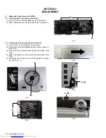
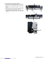
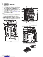
3.1.4 Removing the Top chassis (See Fig.10 to 13)
(1) Remove the six screws
G
attaching the Rear panel. (See
Fig.10)
(2) Remove the two screws
H
attaching the right side of Top
chassis. (See Fig.11)
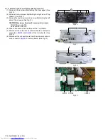
(3) Remove the one screw
J
and one screw
K
attaching the left
side of Top chassis. (See Fig.12)
CAUTION:When remove the screw K, use screw driver is next.
TORX Driver: size T10
Parts number: DR-L70
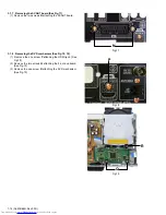
(4) Slide to frontward, and then turnover the Top chassis.
(5) Disconnect the card wires from Micon board connected to
connectors
CN101
and
CN102
of the Amp board. (See
Fig.13)
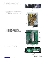
(6) Disconnect the connector wire from Power board connect-
ed to connector
CN103
of the Amp board. (See Fig.13)
Fig.10
Fig.11
Fig.12
Fig.13
G
H
J
K
CN101
CN102
CN103
Summary of Contents for CA-NXF3
Page 45: ... M E M O ...
Page 70: ...3 25 MEMO ...