1-12 (No.MB196)
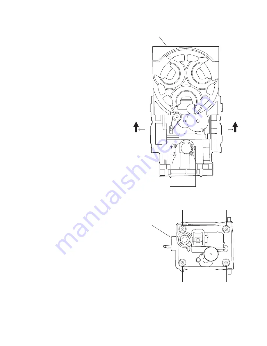
3.2.2 Removing the CD changer mechanism assembly
(See Fig.14 to 15)
• Also remove the CD changer unit.
(1) Turn the CD changer mechanism cover base and remove
the screws
d
connecting the unit to the CD changer mech-
anism assembly.
(2) Removing four screws
e
retaining the CD mechanism hold-
er assembly.
Caution:
When replacing the CD changer mechanism assembly, be
sure not to mistake the positions of the silver color and copper
color spring.
Fig.14
Fig.15
d
CD changer
unit
e
( Green color )
e
( Red color )
e
( Green color )
e
( Red color )
CD changer
mechanism
assembly
Summary of Contents for ca-mxkb4
Page 23: ... No MB196 1 23 ...
Page 27: ...2 1 Wiring diagram ...
Page 28: ...2 2 Block diagrams ...
Page 30: ...2 4 Function control section ...
Page 31: ...2 5 System control section ...
Page 32: ...2 6 FL Key control section ...
Page 33: ...2 7 CD MP3 control section ...
Page 34: ...2 8 Tuner section ...
Page 35: ...2 9 Main board forward side Printed circuit boards ...
Page 36: ...2 10 Main board reverse side ...
Page 37: ...2 11 Front board forward side ...
Page 38: ...2 12 Front board reverse side ...
Page 39: ...2 13 Amp board forward side Amp board reverse side ...
Page 40: ...2 14 Power trans board ...
Page 41: ... M E M O ...


