


(No.MB306)1-11
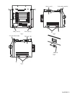
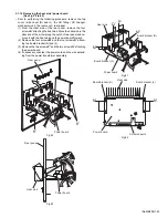
3.1.4 Removing the CD changer mechanism unit
(See Fig.11 to 16)
• Prior to performing the following procedure, remove the top
cover / side cover (R) and (L), and the CD fitting.
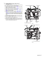
(1) Disconnect the wire from connector
CN601
on the turner
board on the right side of the body.
(2) Disconnect the wire from connector
CN504
on the AUX
board on the inner side of the front panel.
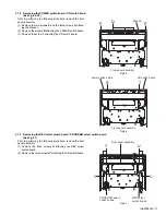
(3) Disconnect the wire from connector
CN801
,
CN802
and
CN803
on the power board.
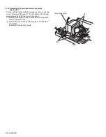
(4) Disconnect the wire from connector
CN100
,
CN101
and
CN207
on the main board at the bottom of the CD changer
mechanism unit, and disconnect the card wire from con-
nector
CN103
. If necessary, release the band attaching the
wires.
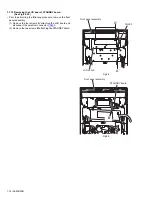
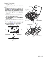
(5) From the side of the body, remove the two screws
F
attach-
ing the CD changer mechanism unit.
(6) From the back of the body, remove the two screws
G
at-
taching the CD changer mechanism unit.
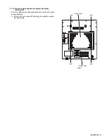
(7) Move the CD changer mechanism unit in the direction of
the arrow while pulling the rear panel backward, and re-
move the CD changer mechanism unit.
Fig.11
Fig.12
Turner board
CN601
AUX board
CN504
Front panel assembly
F
CD changer mechanism unit
Rear panel
Front panel assembly
F
CD changer mechanism unit
Rear panel
Summary of Contents for CA-MXKB22
Page 16: ...1 16 No MB306 Fig 23 Fig 24 f Front panel assembly N N Front panel assembly ...
Page 42: ...2 6 TC9462F U401 TO PICK UP TO CD DECK CD section MX KB22 TO MCU ...
Page 43: ...2 7 CD section MX KB1 TC9462F U401 TOMCU TO MCU ...
Page 52: ...2 16 Main board forward side reverse side Printed circuit boards ...
Page 53: ...2 17 Display board forward side reverse side Power board forward side reverse side ...
Page 55: ...2 19 Speaker jack board Headphone board forward side reverse side ...
Page 71: ...3 15 MEMO ...