background image

– 26 –

English

Specifications

Amplifier section

Output Power (IEC 268-3/DIN)
SUBWOOFERS:

80 W per channel, min. RMS, both channels
driven into 6 

 at 63 Hz with no more than

0.9% total harmonic distortion.

MAIN SPEAKERS: 20 W per channel, min. RMS, both channels

driven into 6 

 at 1 kHz with no more than

0.9% total harmonic distortion.

Audio input sensitivity/Impedance

(at 1 kHz, measured at MAIN SPEAKERS)

AUX:

350 mV/50 k

MIC 1/2: 3.2 mV/5 k

Audio output level:

AUX:

270 mV

Digital output: CD OPTICAL DIGITAL OUTPUT

Signal wave length: 660 nm
Output level: –15 dBm to –12 dBm

Speakers/Impedance: 6 

 – 16 

Tuner

FM tuning range:

87.50 MHz – 108.00 MHz

AM tuning range:

For Saudi Arabia:

At 9 kHz intervals :

531 kHz – 1,602 kHz

At 10 kHz intervals :

530 kHz – 1,600 kHz

For other countries:

At 9 kHz intervals :

531 kHz – 1,710 kHz

At 10 kHz intervals :

530 kHz – 1,710 kHz

CD player

CD Capacity:

3 CDs

Dynamic range:

85 dB

Signal-to-noise ratio:

90 dB

Wow and flutter:

Immeasurable

Cassette deck

Frequency response

Normal (type I): 50 Hz — 14,000 Hz
CrO

2

 (type II):

50 Hz — 14,000 Hz

Metal (type IV): 50 Hz — 14,000 Hz (only for playback)

Wow and flutter

0.15% (WRMS)

General

Power requirement:

AC 110 V / AC 127 V / AC 220 V /
AC 230 V – AC 240 V 

 (adjustable with the

voltage selector), 50 Hz / 60 Hz

Power consumption:

160 W (at operation)
19 W (on standby)

Maximum power consumption (for Taiwan only): 590 W
Dimensions (approx.): 265 mm x 335 mm x 368 mm (W/H/D)

(10

 7

/

16

 in. x 13

 1

/

4

 in. x 14

 1

/

2

 in.)

Mass (approx.):

10.3 kg (22.7 lbs)

Supplied accessories

See page 6.

Design and specifications are subject to change without notice.

EN17-26.MX-J900[U]/f

00.2.22, 1:31 PM

26

Summary of Contents for CA-MXJ900

Page 1: ...ACTO CA MXJ900 For Customer Use Enter below the Model No and Serial No which are located either on the rear bottom or side of the cabinet Retain this information for future reference Model No Serial No GVT0037 003A U INSTRUCTIONS MANUAL DE INSTRUCCIONES INSTRUÇÕES COMPACT DIGITAL AUDIO ...

Page 2: ...uierquesealaposiciónde ajuste del interruptor la alimentación no es cortada completamente La alimentación puede ser controlada remotamente Precaução Interruptor Desconectar o cabo de alimentação para desligar a alimentação por completo Qualquer que seja a posição de ajuste do interruptor a alimentação não é completamente cortada A alimentação pode ser controlada remotamente Warnings Cautions and O...

Page 3: ...ure PRECAUCIÓN Para reducir riesgos de choques eléctricos incendio etc 1 No extraiga los tornillos los cubiertas ni la caja 2 No exponga este aparato a la lluvia o a la humedad PRECAUÇÃO Para reduzir riscos de choques elétricos incêndio etc 1 Não remova parafusos e tampas ou desmonte a caixa 2 Não exponha este aparelho à chuva nem à umidade G 2 ...

Page 4: ...es parte superior parte trasera No se debería colocar nada en las áreas y las distancias que se detallan a continuación 3 Parte inferior Coloque el aparato sobre una superficie recta Debe haber buena circulación de aire para ello coloque el aparato sobre una base a una altura mínima de 10 cm Precaução Ventilação adequada Para evitar riscos de choques elétricos e incêndios e prevenir avarias instal...

Page 5: ...el interior hay radiación láser invisible Evite el contacto directo con el haz 3 PRECAUCIÓN No abra la tapa superior En el interior de la unidad no existen piezas reparables por el usuario deje todo servicio técnico en manos de personal calificado 1 PRODUTO LASER CLASSE 1 2 PERIGO Olaseremiteumarediaçãoinvisívelqueéperigosa caso o aparelho esteja aberto e a trava inoperante ou danificada Evite exp...

Page 6: ...the unit Leave sufficient distance between the unit and the TV Keep the speakers away from the TV to avoid interference with TV DO NOT install the unit in a location near heat sources or in a place subject to direct sunlight excessive dust or vibration We would like to thank you for purchasing one of our JVC products Before operating this unit read this manual carefully and thoroughly to obtain th...

Page 7: ...oadcasts 12 Tuning in a Station 12 Presetting Stations 12 Tuning in a Preset Station 12 Playing Back CDs 13 Loading CDs 13 Playing Back the Entire Discs Continuous Play 13 Basic CD Operations 13 Programming the Playing Order of the Tracks Program Play 14 Playing at Random Random Play 15 Repeating Tracks or CDs Repeat Play 15 Prohibiting Disc Ejection Tray Lock 15 Playing Back Tapes 16 Playing Back...

Page 8: ... z x c v b n m s d f g h j k Location of the Buttons and Controls Become familiar with the buttons and controls on your unit Front Panel Powered Rolling Panel Press PANEL OPEN CLOSE to open the panel To close the panel press the button again Front Panel ...

Page 9: ...ng Panel a PRESET buttons 12 4 reverse search forward search buttons 9 11 14 19 21 23 s REVERSE MODE button 16 19 d REC START STOP button 17 19 f DUBBING button 18 Continued g CD REC START button 18 19 h TAPE A B button 16 j CLOCK TIMER button 9 21 23 k SET button 9 12 14 21 23 l 7 stop button 13 19 TUNING buttons 12 1 fast left fast right buttons 11 14 16 z SEA CONTROL button 11 x PROGRAM RANDOM ...

Page 10: ... START STOP button 17 19 7 TAPE A B button 16 8 1 4 fast left reverse search button 14 16 9 SUBWOOFER buttons 10 p CD 8 button 9 13 Pressing this button also turns on the unit q TAPE 2 3 button 9 16 Pressing this button also turns on the unit w Standby On button 9 e SLEEP button 23 r ECHO button 20 t FM MODE button 12 y REPEAT button 15 u CANCEL button 9 15 21 i SET button 9 12 14 21 23 o 7 stop b...

Page 11: ...Ω COAXIAL terminal 2 Extend the FM antenna 3 Fasten it up in the position which gives you the best reception then fix it on the wall etc About the supplied FM antenna The FM antenna supplied with this unit can be used as temporary measure If reception is poor you can connect an outdoor FM antenna To connect an outdoor FM antenna Before connecting it disconnect the supplied FM antenna FM antenna su...

Page 12: ... must remain connected For better reception of both FM and AM Make sure the antenna conductors do not touch any other terminals and connecting cords Keep the antennas away from metallic parts of the unit connecting cords and the AC power cord AM antenna Vinyl covered wire not supplied AM loop antenna supplied Connecting Speakers COAXIAL ANTENNA AM LOOP FM 75 AM EXT 2 3 1 Blue Speaker cord blue bla...

Page 13: ...lamp IMPORTANT Use only speakers with the same speaker impedance as indicated by the speaker terminals on the rear of the unit Connecting Other Equipment You can connect both analog and digital equipment DO NOT connect any equipment while the power is on DO NOT plug in any equipment until all connections are complete To connect an analog component Be sure that the plugs of the audio cords are colo...

Page 14: ... playing any source Each time you press the button the source indication and the clock time alternate on the display To adjust the clock again If you have adjusted the clock before you need to press CLOCK TIMER repeatedly until the clock setting mode is selected Each time you press the button the clock timer setting modes change as follows If there is a power failure The clock loses the setting an...

Page 15: ...estore the sound press the button again Reinforcing the Bass Sound The SUBWOOFER VOLUME control provided for this unit can enhance the subwoofer sound if subwoofers are connected to the rear of this unit see page 7 This function only affects the playback sound but does not affect your recording Turn the SUBWOOFER VOLUME control clockwise to increase the subwoofer sound or counterclockwise to decre...

Page 16: ...n be stored in the MANUAL 1 2 and 3 modes There is a time limit in doing the following steps If the setting is canceled before you finish start from step 1 again If you want to add the surround elements in your SEA pattern select one of the surround modes D CLUB HALL or STADIUM before starting the procedure below On the unit ONLY 1 Press and hold SEA CONTROL until SEA CONT appears on the display 2...

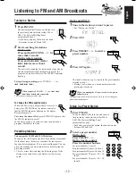
Page 17: ...tions In some cases test frequencies have been already memorized for the tuner since the factory examined the tuner preset function before shipment This is not a malfunction You can preset the stations you want into memory by following the presetting method There is a time limit in doing the following steps If the setting is canceled before you finish start from step 1 again On the unit ONLY 1 Tun...

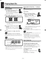
Page 18: ... Continuous Play You can play CDs continuously 1 Load CDs 2 Press one of the disc number buttons CD1 CD2 and CD3 for the disc you want to play CD play starts from the first track of the selected disc Pressing CD 8 instead of the disc number buttons starts playing back if a CD is on the trays To stop during play press 7 To remove the disc press 0 for the corresponding disc tray CD playback sequence...

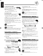
Page 19: ...ad CDs If the current playing source is not the CD player press CD 8 then 7 before going to the next step 2 Press PROGRAM RANDOM repeatedly until PROGRAM appears on the display If a program has been stored in memory the program is called up Each time you press the button CD play mode changes as follows 3 Press one of the disc number buttons CD1 CD2 and CD3 to select the disc number you want to pla...

Page 20: ...7 UNLOCKED appears for a while and the loaded CDs are unlocked If you try to eject CDs LOCKED appears to inform you that the Tray Lock is in use To check the program contents Before playing you can check the program contents by pressing 1 4 or on the remote control Shows the programed tracks in the programed order 1 4 Shows them in the reverse order To modify the program Before playing you can era...

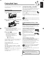
Page 21: ...t the Reverse Mode indicator on the display lights up like To cancel Reverse Mode press the button again so that the Reverse Mode indicator on the display lights up like When Reverse Mode is on with cassettes in both decks A and B After the reverse 2 side of the tape finishes playing the tape in the other deck starts playing Locating the Beginning of a Song Music Scan You can use Music Scan to loc...

Page 22: ...verse Mode indicator lights up as IMPORTANT It may be unlawful to record or play back copyrighted material without the consent of the copyright owner The recording level is automatically set correctly so it is not affected by the VOLUME control and the SUBWOOFER VOLUME control Thus during recording you can adjust the sound you are actually listening to without affecting the recording level While r...

Page 23: ...eginning of the reverse side 2 If you start recording on the reverse side 2 recording will stop when recording is done only on one side reverse of the tape To cancel Reverse Mode press the button again so that the Reverse Mode indicator lights up as To record an AM station Beat Cut While recording an AM broadcast beats may be heard which are never heard when listening to the broadcast without reco...

Page 24: ...verse side SIDE B alternate 5 Put a recordable cassette of appropriate length into deck B 6 Press REVERSE MODE so that the Reverse Mode indicator lights up as Without turning on the Reverse Mode recording will stop when the front side of the tape is recorded 7 Press CD REC START The REC recording indicator lights up on the display Deck B starts recording then about 10 seconds later the CD player s...

Page 25: ...he MIC LEVEL and VOLUME controls Avoid pointing the microphone s towards the speakers When two microphones are connected turn off the On Off switch on the unused microphone If you use the following sources as the playing source for Vocal Masking you cannot get the satisfactory results Radio programs a radio signal is not as reliable as the signals coming from a tape or CD Monaural sources Poorly d...

Page 26: ...icator A or B is lit on the display Make sure that the tape direction is correct When using the external component as the source to play set the timer equipped with the external component at the same time On the unit ONLY 1 Press CLOCK TIMER until DAILY appears on the display The DAILY Daily Timer indicator also starts flashing on the display Each time you press the button the timer setting modes ...

Page 27: ...The DAILY Daily Timer indicator lights up on the display The settings you have done are shown on the display in sequence for your confirmation If the unit is turned on when the timer on time comes Daily Timer does not work Using Recording Timer With Recording Timer you can make a tape of a radio broadcast automatically How Recording Timer actually works The unit automatically turns on tunes into t...

Page 28: ...EP indicator does not go off 4 Set the on time you want the unit to turn on 1 Press 4 or to set the hour then press SET 2 Press 4 or to set the minute then press SET OFF TIME appears for 2 seconds then the unit enters off time setting mode 5 Set the off time you want the unit to turn off on standby 1 Press 4 or to set the hour then press SET 2 Press 4 or to set the minute then press SET The unit e...

Page 29: ...rect sunlight or heat In moist areas Near a magnet Handling discs Remove the disc from its case by holding it at the edge while pressing the center hole lightly Do not touch the shiny surface of the disc or bend the disc Put the disc back in its case after use to prevent warping Be careful not to scratch the surface of the disc when placing it back in its case Avoid exposure to direct sunlight tem...

Page 30: ...isc is scratched or dirty The AC power cord is not plugged in Trays are locked The disc is placed upside down Power supply from the AC power cord has been cut off while the tape was running Small tabs on the back of the cassette are removed Vocal Masking is activated The built in microprocessor may malfunction due to external electrical interference The path between the remote control and the remo...

Page 31: ...9 kHz intervals 531 kHz 1 602 kHz At 10 kHz intervals 530 kHz 1 600 kHz For other countries At 9 kHz intervals 531 kHz 1 710 kHz At 10 kHz intervals 530 kHz 1 710 kHz CD player CD Capacity 3 CDs Dynamic range 85 dB Signal to noise ratio 90 dB Wow and flutter Immeasurable Cassette deck Frequency response Normal type I 50 Hz 14 000 Hz CrO2 type II 50 Hz 14 000 Hz Metal type IV 50 Hz 14 000 Hz only f...

Page 32: ...sition of the voltage selector switch provided on the outside of this equipment and if different reset the voltage selector switch to prevent from damage or risk of fire electric shock IMPORTANTE para la línea de la red CA ANTES DE ENCHUFAR EL EQUIPO compruebe si la tensión de la línea de la red CA corresponde con la posición del selector de tensión situado en la parte exterior del equipo y si es ...

Reviews: