background image

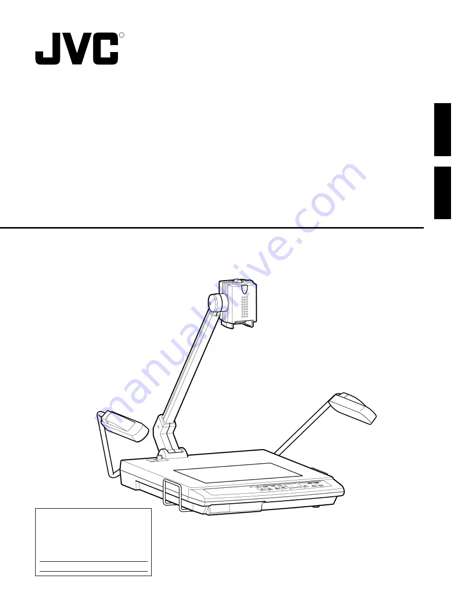
AV-P1000U

SS961490-002

DIGITAL PRESENTER

MANUEL D’INSTRUCTIONS  : PRESENTOIR NUMÉRIQUE

OPERATING INSTRUCTIONS

R

For Customer Use:

Enter below the Serial No. which 
are located on the fram. 
Retain this information for future 
reference.

Model No. AV-P1000U

Serial No.

This instruction book is made from 100% recycled paper.

ENGLISH

FRAN

Ç

AIS

Summary of Contents for AV-P1000U

Page 1: ... PRESENTOIR NUMÉRIQUE OPERATING INSTRUCTIONS R For Customer Use Enter below the Serial No which are located on the fram Retain this information for future reference Model No AV P1000U Serial No This instruction book is made from 100 recycled paper ENGLISH FRANÇAIS ...

Page 2: ...e required to correct the interference at his own ex pense Information for Canada This product complies with D O C limits C R C C 1374 pertaining to class A digital apparatus Informations pour le Canada Ce produit est en conformité avec les normes D O C C R C C 1374 concernant les appareils numériques de classe A The instructions are given in two languages English from page 2 to 21 and French from...

Page 3: ... as cloth or paper on or near this unit during use Clean this unit by wiping dirt off with a cloth moistened with detergent Wipe dry with a dry cloth Do not expose this unit to volatile liquids such as thinner benzene or insecticide Damage or discoloration could result FEATURES High precision presentation system capable of projecting images of a wide range of physical objects including 3 dimension...

Page 4: ...TS buttons Use to adjust and set the camera p 14 9 IRIS adjust buttons Use to adjust picture brightness p 13 0 VIDEO OUT button Use to switch between RGB output and video output p 12 LIGHTS button Use to turn the side and back illumination on off p 13 Power indicator when power is switched on it will glow green Side Lamp Camera arm Camera head rotation knob Side Lamp Stage Control panel Rear panel...

Page 5: ... added to the video signal output at the RGB OUT1 G connector and RGB OUT2 connector C Sets whether or not the on screen display signal is output to the video signal output at the RGB OUT1 and 2 connectors On screen signals are output to the VIDEO OUT connector regardless of the mode setting The default setting at the factory is A 1 B 1 C 1 and D 1 3 REMOTE IN connector Connect a personal computer...

Page 6: ...display or monitor and make the appropriate connections BNC Connection D sub 15 pin Connection 4 3 RGB OUT1 R G B Hs Cs Vs RGB OUT2 SYNC REMOTE IN RS 232C MODE 0 1 A B C D 1 2 To the RGB OUT1 connectors To video input connectors RGB OUT1 Display BNC BNC cable RGB OUT1 R G B Hs Cs Vs 4 3 RGB OUT1 R G B Hs Cs Vs RGB OUT2 SYNC REMOTE IN RS 232C MODE 0 1 A B C D 1 2 Male To the RGB OUT2 connector Male...

Page 7: ...release button 4 Then fold the camera arm down in the direction shown 5 until it stops and lock it Notes Do not release the camera arm when the lock release but ton is pressed in Otherwise a malfunction or injury may result When the camera arm is locked do not apply excessive force to it Otherwise a malfunction may occur For storage do not lean this unit against a wall etc If it falls over a malfu...

Page 8: ...age of a large object such as the page of an encyclopedia pull out the book holder in the direction shown 6 2 Presenting slide films Turn on the side illumination and insert the film into the slide film holder 7 Then adjust the size of the picture with the ZOOM buttons 1 When the picture size is determined ad just the focus with the FOCUS buttons 2 Notes Do not apply excessive force to the book ho...

Page 9: ...USTMENTS p 14 and 15 To shoot the face of a person or nearby objects such as a blackboard remove the close up lens by turning it in the direction shown 8 Then direct the camera head in the di rection shown 9 and turn the camera head rotation knob 180 degrees in the direction shown 0 If the brightness is insufficient adjust with the IRIS buttons 4 Shooting nearby objects 0 8 9 To shoot the stage se...

Page 10: ...s You can use the ON SCREEN ADJUSTMENTS to change the maximum magnification setting p 14 and 15 Note When video signals are output to theVIDEO OUT con nector the picture cannot be enlarged with the digital zoom function ZOOM PRESET Two frequently used picture sizes can be stored in memory Set the required size and press the PRESET 1 or 2 button for 2 seconds or more P1 or P2 appears in the upper l...

Page 11: ...ZOOM FOCUS FAR NEAR WIDE TELE LIGHTS IRIS MENU ENTER VIDEO OUT PC FREEZE AUTO WHITE SET DIGITAL PRESET 1 2 Note Focusing range is up to 100 mm from the stage sur face Even though the auto white set mode is engaged the tone is not adjusted unless this button is pressed When the lighting changes perform the auto white set op eration again The auto white set mode and the manual mode can be switched w...

Page 12: ...ER VIDEO OUT PC FREEZE AUTO WHITE SET DIGITAL PRESET 1 2 Notes Signals received via the PC IN connector cannot be output to the VIDEO OUT connector Thin lines in the camera picture may flicker on the monitor screen when the camera signal is output via the VIDEO OUT connector When digital zoom is activated signals cannot be output to the VIDEO OUT connector During video output the FREEZE button wil...

Page 13: ...tor blinks for about 2 seconds and lights then the back illumination lights When the back illumination is lit press this button The indicator and the back illumination go out LIGHTS ON SCREEN ADJUSTMENTS ZOOM FOCUS FAR NEAR WIDE TELE LIGHTS IRIS MENU ENTER VIDEO OUT PC FREEZE AUTO WHITE SET DIGITAL PRESET 1 2 ON SCREEN ADJUSTMENTS ZOOM FOCUS FAR NEAR WIDE TELE LIGHTS IRIS MENU ENTER VIDEO OUT PC F...

Page 14: ...CE RED LEVEL BLUE LEVEL IRIS MODE IRIS LEVEL TEXT MODE Info OFF ON AW SET 0 0 AUTO 0 ON Item Menu screen Set value 4 To set another item press the or button to set the mark When the mark is set to DIGITAL ZOOM at the lowest line on page 1 press the button to show the menu on page 2 When the mark is set to ZOOM PRESET 1 at the top line press the button to go to the menu on page 1 WHITE BALANCE DIGI...

Page 15: ...ions are stored in the status memory ZOOM PRESET 1 ZOOM PRESET 2 Use to set the picture size to be called with the ZOOM PRESET buttons Different sizes can be set for 1 and 2 Set this function to USER to save the specified size by pressing the ZOOM PRESET 1 or 2 for more than 2 seconds BW COLOR COLOR B W COLOR Use to show a picture in black and white When this is used to show a black and white docu...

Page 16: ...value to 0 PICTURE MEMORY 4 Up to 3 pictures from the camera can be stored in memory as still images When the picture you want to store is displayed press one of the PICTURE MEMORY buttons 1 to 3 for more than 2 seconds to store it in memory In the upper left of the screen M1 M2 or M3 will appear briefly to confirm the image has been saved To call a stored picture press one of the PICTURE MEMORY b...

Page 17: ...inverter fluorescent light flash light etc hits the remote control light reception section the remote control may not work properly In this case change the direction of this unit or the illumination When there is a person or an object between the remote control and the light reception section signal reception may not be possible If the remote control is dropped or a violent shock is applied to it ...

Page 18: ...the zoom iris etc by checking the picture on the local monitor 4 When you have completed all necessary adjustments press the VIDEO OUT button again The new item is shown on the display This method is recommended when showing items of different sizes and when using the zoom and iris etc By taking advantage of this presenter s many features you can conduct a more effective presentations Notes Depend...

Page 19: ...4 Set the computer s RS 232C communication settings as specified in the interface specifications 5 Start up the control program on the computer Interface specifications Communication method Full duplex asynchronous Baud rate 9600 bps Start bit 1 bit Stop bit 1 bit Data length 8 bits Parity Even parity RS 232C Cable Connection to a serial port AV P1000 PC D sub 9 pin female D Sub 9 pin female CD 1 ...

Page 20: ... with the pixels in the camera image device and color stripes may occur In this case change the picture size slightly with the ZOOM buttons Did you adjust the tone with the AUTO WHITE SET p 11 Is the set value for RED LEVEL and BLUE LEVEL of the ON SCREEN ADJUSTMENTS opti mum When this unit is used near equipment generating a strong electric wave or a digital device such as a personal computer bea...

Page 21: ...al V Vertical 1280 dots x 960 dots H 64 0 kHz V 60 0 Hz 1024 dots x 768 dots H 48 4 kHz V 60 0 Hz 800 dots x 600 dots H 37 9 kHz V 60 3 Hz 640 dots x 480 dots H 31 5 kHz V 59 9 Hz Interlace NTSC H 15 734 kHz V 59 95 Hz Image pickup device 1 2 7 interline transfer CCD Number of pixels effective 1 300 000 H1288 x V968 Frame rate 4 3 fps Synchronization system Internal White balance Auto white set wi...

Page 22: ...lammables comme le tissu ou le papier sur ou à proximité de l appareil pendant son utilisation Nettoyer cet appareil en essuyant la poussière avec un chiffon humidifié d un détergent Sécher l appareil avec un chiffon sec Ne pas exposer cet appareil aux liquides volatils comme les diluants le benzène ou les insecticides Des dommages ou une décoloration risquent de se produire CARACTERISTIQUES Systè...

Page 23: ...C IN p 31 8 Touches de réglages à l écran ON SCREEN ADJUSTMENTS S utilise pour régler la caméra p 33 9 Touches de réglage IRIS S utilise pour allumer et éteindre les éclairages latéraux et arrière p 32 0 Touche de sortie vidéo VIDEO OUT S utilise pour commuter entre les sorties RGB et vidéo p 31 Touches d éclairage S utilise pour régler la luminosité de l image p 32 Indicateur de puissance Lorsque...

Page 24: ...e de télécommande REMOTE IN Connectez un ordinateur personnel à ce connecteur pour le commander à distance p 37 4 Connecteurs RGB OUT1 Envoient en sortie les signaux de la caméra ou du connecteur PC IN ainsi que ceux de synchronisation connecteurs BNC 5 Connecteur RGB OUT2 Envoie en sortie les signaux de la caméra ou du connecteur PC IN ainsi que ceux de synchronisation Connecteur D sub à 15 broch...

Page 25: ...r VIDEO OUT Vers le connecteur d entrée vidéo Câble vidéo fourni VIDEO OUT 5 Connectez le câble d alimentation au connecteur AC IN et branchez l autre extrémité à une prise du secteur Appuyez sur l interrupteur d alimentation pour mettre l appareil sous tension Remarque Ne pas oublier de couper l alimentation pour protéger cet appareil et les autres équipements connectés Ne pas connecter d apparei...

Page 26: ...qué en 5 jusqu à ce qu il s arrête et verrouillez le Remarque Ne pas libérer le bras de la caméra lorsque la touche de déverrouillage est enfoncée Sinon il y a risque de dysfonctionnement ou de blessure corporelle Lorsque le bras de la caméra est verrouillé ne pas exercer dessus d effort excessif Sinon un dysfonctionnement peut se produire Lors du rangement de l appareil ne pas l appuyer contre un...

Page 27: ...apture de l image d un objet de taille importante comme la page d une encyclopédie tirez le support de livre dans le sens indiqué 6 2 Présentation de films diapositifs Allumez l éclairage latéral et introduisez le film dans le sup port de diapo 7 Ensuite réglez le format de l image avec les touches ZOOM 1 Lorsque les dimensions de l image sont satisfaisantes réglez la mise au point optique avec le...

Page 28: ...33 et 34 Pour filmer le visage d une personne ou des objets proches tel qu un tableau noir retirez l objectif macro en le tournant dans le sens indiqué 8 Puis dirigez la tête de la caméra dans le sens indiqué 9 et tournez le bouton de rotation de la tête de la caméra knob sur 180 degrées dans le sens indiqué 0 Si la luminosité est insuffisante réglez la avec les touches IRIS 4 Prise de vue d objet...

Page 29: ...odifier le réglage d agrandissement maximum p 33 et 34 Remarque Lorsque des signaux vidéo sont envoyés en sortie au connecteur VIDEO OUT l image ne peut pas être agrandie avec la fonction zoom numérique ZOOM PREREGLE Deux formats d image fréquemment utilisés peuvent être enregistrés en mémoire Réglez le format souhaité et appuyez sur la touche PRESET 1 ou 2 pendant 2 secondes ou plus P1 ou P2 appa...

Page 30: ...ON SCREEN ADJUSTMENTS ZOOM FOCUS FAR NEAR WIDE TELE LIGHTS IRIS MENU ENTER VIDEO OUT PC FREEZE AUTO WHITE SET DIGITAL PRESET 1 2 Remarque La distance de mise au point optique va jusqu à 100 mm de la surface de la scène Même si le mode de réglage automatique de la balance des blancs est activé la tonalité n est pas réglée tant que l on appuie pas sur cette touche Lorsque l éclairage change effectue...

Page 31: ...UTO WHITE SET DIGITAL PRESET 1 2 Remarque Les signaux reçus par le connecteur PC IN ne peuvent être envoyés en sortie vers le connecteur VIDEO OUT De fines lignes peuvent scintiller sur l image de la caméra à l écran du moniteur lorsque le signal de la caméra est émis par le connecteur VIDEO OUT Lorsque le zoom numérique est activé les signaux ne peuvent être envoyés en sortie au connecteur VIDEO ...

Page 32: ...e touche L indicateur clignote pendant environ 2 secondes et s allume l éclairage arrière s allume ensuite Lorsque l éclairage arrière est allumé appuyez sur cette touche L indicateur et the back l éclairage arrière s éteignent ECLAIRAGE ON SCREEN ADJUSTMENTS ZOOM FOCUS FAR NEAR WIDE TELE LIGHTS IRIS MENU ENTER VIDEO OUT PC FREEZE AUTO WHITE SET DIGITAL PRESET 1 2 ON SCREEN ADJUSTMENTS ZOOM FOCUS ...

Page 33: ...ON AW SET 0 0 AUTO 0 ON Elément Ecran de menu Valeur de réglage 4 Pour régler un autre élément appuyez sur les touches ou pour positionner la marque Lorsque la marque est placée sur ZOOM DIGITAL sur la ligne la plus basse de la page 1 appuyez sur la touche pour afficher le menu à la page 2 Lorsque la marque est placée sur ZOOM PRESET 1 à la ligne supérieure appuyez sur la tou che pour aller au men...

Page 34: ... ZOOM PRESET 1 ZOOM PRESET 2 S utilise pour régler le format de l image à être appelé avec les touches de ZOOM PRESET Différent formats peuvent être réglés pour 1 et 2 Réglez cette fonction sur USER pour enregistrer le format particulier en appuyant sur la touche ZOOM PRESET 1 ou 2 pendant plus de 2 secondes BW COLOR COLOR B W COLOR S utilise pour pour montrer une image en noir blanc Lorsque cette...

Page 35: ...haitez enregistrer est affichée appuyez sur une des touches PICTURE MEMORY 1 à 3 pendant plus de 2 secondes pour l enregistrer en mémoire L indication M1 M2 ou M3 apparaît brièvement à la partie supérieure gauche de l écran pour confirmer l enregistrement Pour rappeler une image enregistrée appuyez sur une des touches PICTURE MEMORY 1 à 3 Appuyez à nouveau sur cette même touche pour revenir à l im...

Page 36: ...orescent inversée lampe torche etc atteint cette zone de réception du rayon de la télécommande celle ci risque de ne pas fonctionner correctement Dans ce cas déplacez l appareil ou l éclairage Lorsqu une personne ou un objet se trouve entre la télécommande et la section de réception du rayon la réception du signal risque d être impossible Si la télécommande tombe à terre ou est soumise à un choc v...

Page 37: ...ents et réglez le zoom l iris etc en vérifiant l image sur le moniteur local 4 Lorsque vous avez terminé tous les réglages nécessaires appuyez à nouveau sur la touche VIDEO OUT Le nouvel élément est affiché Cette méthode est recommmandé pour montrer des éléments de formats différents et lors de l utilisation du zoom de l iris etc Vous pouvez profiter des nombreuses fonctions de ce présentateur et ...

Page 38: ... les réglages de communication RS 232C de l ordinateur d après les caractéristiques de l interface 5 Démarrez le programme de contrôle sur l ordinateur Caractéristiques de l interface Méthode de communication Duplex asynchrone total Vitesse de transmission 9600 bps Bit de départ 1 bit Bit d arrêt 1 bit Largeur des données 8 bits Parité Paire Câble RS 232C Connexion à un port série AV P1000 PC D su...

Page 39: ...es pixels de la cellule de capture de la caméra et des bandes de couleur peuvent se produire Dans ce cas changez légèrement le format de l image avec les touches ZOOM Est ce que vous avez effectué le réglage automatique de la tonalité avec AUTO WHITE SET p 30 Est ce que la valeur réglée de NIVEAU DE ROUGE et NIVEAU DE BLEU des réglages à l écran est optimale Lorsque cet appareil est utilisé à prox...

Page 40: ...ie Fréquence de balayage progres sive H Horizontal V Vertical 1280 x 960 points H 64 kHz V 60 Hz 1024 x 768 points H 48 4 kHz V 60 Hz 800 x 600 points H 37 9kHz V 60 3Hz 640 x 480 points H 31 5kHz V 59 9Hz Entrelacé NTSC H 15 734kHz V 59 95Hz CARACTÉRISTIQUES TECHNIQUES Dispositif de capture d image Cellule CCD à transfert d interligne de 1 2 7 Nombre de pixels effectif 1 300 000 H1288 x V968 Imag...

Reviews: