


1-48 (No.YA318)
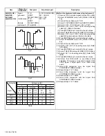
SUB BRIGHT
adjustment
Signal
generator
Remote
control unit
[1.PICTURE/SOUND]
S03: BRIGHT
(1) Receive NTSC signal.
(2) Select STANDARD mode with [VIDEO STATUS] key.
(3) Set the COLOR TEMP is LOW mode.
(4) Select 1.PICTURE/SOUND from SERVICE MENU.
(5) Select < S03 > (BRIGHT).
(6) Set the initial setting value. (See Table 1)
(7) If the brightness is not the best with the initial setting
value, make fine adjustment until you get the best
brightness.
(8) Press [MUTING] key to memorize the set values.
(9) Select THEATER mode with [VIDEO STATUS] key.
(10) Repeat steps 4 to 8 above.
(11) Input 480i component signal from COMPONENT
VIDEO terminal.
(12) Repeat steps 2 to 10 above.
(13) Input 1080i component signal from COMPONENT
VIDEO terminal.
(14) Repeat steps 2 to 10 above.
Table 1
SUB
CONTRAST
adjustment (1)
Signal
generator
Remote
control unit
[1.PICTURE/SOUND]
S04: CONTRAST
[ Method of adjustment without measuring instrument ]
(1) Receive NTSC gray scale signal.
(2) Select STANDARD mode with [VIDEO STATUS]
key.
(3) Set the COLOR TEMP is LOW mode.
(4) Select 1.PICTURE/SOUND from SERVICE MENU.
(5) Select < S04 > (CONTRAST).
(6) Set the initial setting value. (See Table 2)
(7) If the contrast is not the best with the initial setting
value, make fine adjustment of the < S04 > until you
get the optimum contrast.
(8) Press [MUTING] key to memorize the set values.
(9) Select THEATER mode with [VIDEO STATUS] key.
(10) Repeat steps 4 to 8 above.
(11) Input 480i component black & white signal from
COMPONENT VIDEO terminal.
(12) Repeat steps 2 to 9 above.
(13) Receive 1080i component black & white signal from
COMPONENT VIDEO terminal.
(14) Repeat steps 2 to 9 above.
Table 2
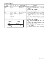
SUB
CONTRAST
adjustment (2)
Signal
generator
Oscilloscope
Remote
control unit
TP-G
[G CRT
SOCKET PWB]
[1.PICTURE/SOUND]
S04: CONTRAST
[ Method of adjustment with measuring instrument ]
(1) Receive NTSC gray scale signal.
(2) Select STANDARD mode with [VIDEO STATUS] key.
(3) Select FULL mode with [ASPECT] key.
(4) Set the COLOR TEMP is LOW mode.
(5) Connect the oscilloscope to TP-G.
(6) Select 1.PICTURE/SOUND from SERVICE MENU.
(7) Select < S04 > (CONTRAST).
(8) Adjust < S04 > so that the 0% signal portion and the
100% signal portion of both sides may become the
follow table voltage.
(9) Press [MUTING] key to memorize the set value.
(10) Select THEATER mode with [VIDEO STATUS] key.
(11) Repeat steps 8 to 9 above.
(12) Receive 480i component gray scale signal.
(13) Repeat steps 2 to 9 above.
(14) Set 1080i component gray scale signal.
(15) Repeat steps 2 to 9 above.
Table 3
Item
Measuring
instrument
Test point
Adjustment part
Description
Signal
Item
S03
NTSC
480i
1080i
Setting value
127
127
127
Signal
Item
S04
NTSC
480i
1080i
Setting value
052
061
061
Video status
STANDARD
102V
104V
100V
THEATER
102V
104V
94V
NTSC
480i
1080i
SETTING VOLTAGE [AV-48P776 / AV-48P786]
Video status
STANDARD
86V
92V
86V
THEATER
84V
92V
86V
NTSC
480i
1080i
SETTING VOLTAGE [AV-56P776 / AV-56P786]
Signal
Signal
Summary of Contents for AV-48P776/H
Page 1: ......
Page 92: ... No YA318 2 4 ...
Page 135: ...2 47 No YA318 PATTERN DIAGRAMS MAIN PWB PATTERN SOLDER SIDE ...
Page 136: ... No YA318 2 48 FRONT ...
Page 137: ...2 49 No YA318 MAIN PWB PATTERN PARTS SIDE ...
Page 138: ... No YA318 2 50 FRONT ...