


1-16 (No.YA318)
3.2
MEMORY IC REPLACEMENT
• This model uses the memory IC.
• This memory IC stores data for proper operation of the video and drive circuits.
• When replacing, be sure to use an IC containing this (initial value) data.
3.2.1 MEMORY IC LIST
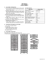
3.2.2 MEMORY IC REPLACEMENT PROCEDURE
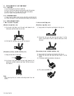
1. POWER OFF
Switch off the power and disconnect the power plug.
2. REPLACE THE MEMORY IC
Be sure to use the memory IC written with the initial setting
values.
3. POWER ON
Connect the power plug to the AC outlet and switch on the
power.
4. RECEIVING CHANNEL SETTING
Refer to the OPERATING INSTRUCTIONS and set the
receive channels (Channels Preset) as described.
5. USER SETTING
Check the user setting items according to the given in page
later. Where these do not agree, refer to the OPERATING
INSTRUCTIONS and set the items as described.
6. SERVICE MODE SETTING
Verify what to set in the SERVICE MODE, and set whatever is
necessary. Refer to the INITIAL SETTING VALUE OF
SERVICE MENU.
3.2.3 SERVICE ADJUSTMENT ITEM
Simbol
Number of pins
Mounting PWB
Main content of data
IC1803
8-pin
MAIN PWB
Initial setting data is memorized.
Setting items
Settings
Item No.
1.PICTURE/SOUND
(Video / Audio setting)
Audio circuits (A)
Adjust A01 to A27
Video circuits (S)
Adjust S01 to S99
Deflection circuits (D)
Adjust D01 to D32
Factory setting items (F)
Fixed
F01 to F86
2.YC SEP
(3D YC separation setting)
[Do not adjust]
Fixed
YCM001 to YCM131
3.WHITE BALANCE
(White balance adjustment)
Adjust
BR
DRV R
DRV B
CUT R
CUT G
CUT B
4.MEMORY SETUP
(Memory data edit)
[Do not adjust]
5.RF AFC
(AFC setting)
[Do not adjust]
Fixed
---
6.CONVER A
(Convergence adjustment)
Adjust CPA01 to CPA11
Adjust CCA01 to CCA12
Adjust CBA01 to CBA94
7.CONVER B
(Convergence adjustment)
Adjust
---
8.IP
(DIST processing setting)
[Do not adjust]
Fixed
IPA001 to IPA042
9.DSD
(Digital super detail setting)
[Do not adjust]
Fixed
DSA001 to DSA053
Fixed
DSB001 to DSB053
Fixed
DSC001 to DSC044
Fixed
DSD001 to DSD017
0.HDMI
(Digital input processing setting)
[Do not adjust]
Fixed
HDM001 to HDM080
Fixed
RHD001 to RHD170
SERVICE MODE MAIN MENU
1.PICTURE/SOUND
2.YC SEP
3.WHITE BALANCE
4.MEMORY SETUP
5.RF AFC
6.CONVER A
7.CONVER B
8.IP
9.DSD
0.HDMI
Summary of Contents for AV-48P776/H
Page 1: ......
Page 92: ... No YA318 2 4 ...
Page 135: ...2 47 No YA318 PATTERN DIAGRAMS MAIN PWB PATTERN SOLDER SIDE ...
Page 136: ... No YA318 2 48 FRONT ...
Page 137: ...2 49 No YA318 MAIN PWB PATTERN PARTS SIDE ...
Page 138: ... No YA318 2 50 FRONT ...