


No.52003
AV-36F703
AV-36F713
AV-36F803
27
Item
Measuring
instrument
Test point
Ad justment part
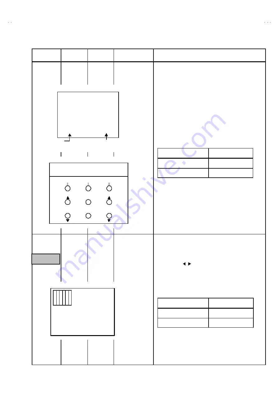
Description
WHITE
BALANCE
(High Lig ht)
adjustment
Signal
generator
Remote
control unit
S14:R DRIVE
S15:B DRIVE
1. Receive the blac k-and-white signal ( color off ).
2. Enter to the SERVICE MENU mode.
3. Select
the
HIGH LIG
HT mode in the SERVICE MENU.
4. Set the initial setting value of
S14:R DRIVE
and
S15:B DRIVE
with the
④
④
④
④
,
⑥
⑥
⑥
⑥
,
⑦
⑦
⑦
⑦
and
⑨
⑨
⑨
⑨
keys of the remote c ontrol unit.
5. Adjust the screen until it becomes white using the
④
④
④
④
,
⑥
⑥
⑥
⑥
,
⑦
⑦
⑦
⑦
and
⑨
⑨
⑨
⑨
keys of the remote c ontrol unit.
(NOTE)
The
③
③
③
③
EXIT key is the cancel key for the W HIT E BALANCE.
PIP WHITE
BALANCE
(High Lig ht)
adjustment
Signal
generator
Remote
control unit
PIP08:R DRIVE
PIP10:B DRIVE
1. Receive the blac k-and-white signal ( color off ).
2. Enter to the SERVICE MENU mode.
3. Select
the
PIP08:R DRIVE
,
PIP10:B DRIVE
, of the
5.PIP(PIP)
SERVICE MENU.
4. Set the corresponding initial setting values with the
FUNCTION ( / ) key of the remote control unit.
5. Adjust the
PIP08:R DRIVE, PIP10:B DRIVE
until the s creen
becomes white.
***
***
(R)
(B)
[WHITE SCREEN]
Ad justment item
Initial setting value
S14 R DRIVE
64
S15 B DRIVE
64
REMOTE CONTROL UNIT
H.LINE ON
EXIT
H.LINE OFF
R DRIVE
R DRIVE
B DRIVE
1
4
7
2
5
8
3
6
9
B DRIVE
Ad justment item
Initial setting value
PIP08 R DRIVE
63
PIP10 B DRIVE
65
Only for
AV-36F803
/Y