No. 52003
AV-36F703
AV-36F713
AV-36F803
10
MEMORY IC REPLACEMENT
1. Memory IC
This TV uses memory IC.
This memory IC stores data for proper operation of the video and deflection circuits.
When replacing the memory IC, be sure to use an IC containing this (initial value) data.
2. Memory IC replacement procedure
(1) Power off
Switch off the power and disconnec t the power plug from the AC
outlet.
(2) Replace the memory IC
Be sure to use a memory IC written with the initial s etting data.
(3) Power on
Connect the power plug to the AC outlet and switc h on the power.
(4) Confirm the system constant value
"
Normally,do not adjust the 12.SYSTEM (SYS).
"
When adjust, be sure to input the signal.
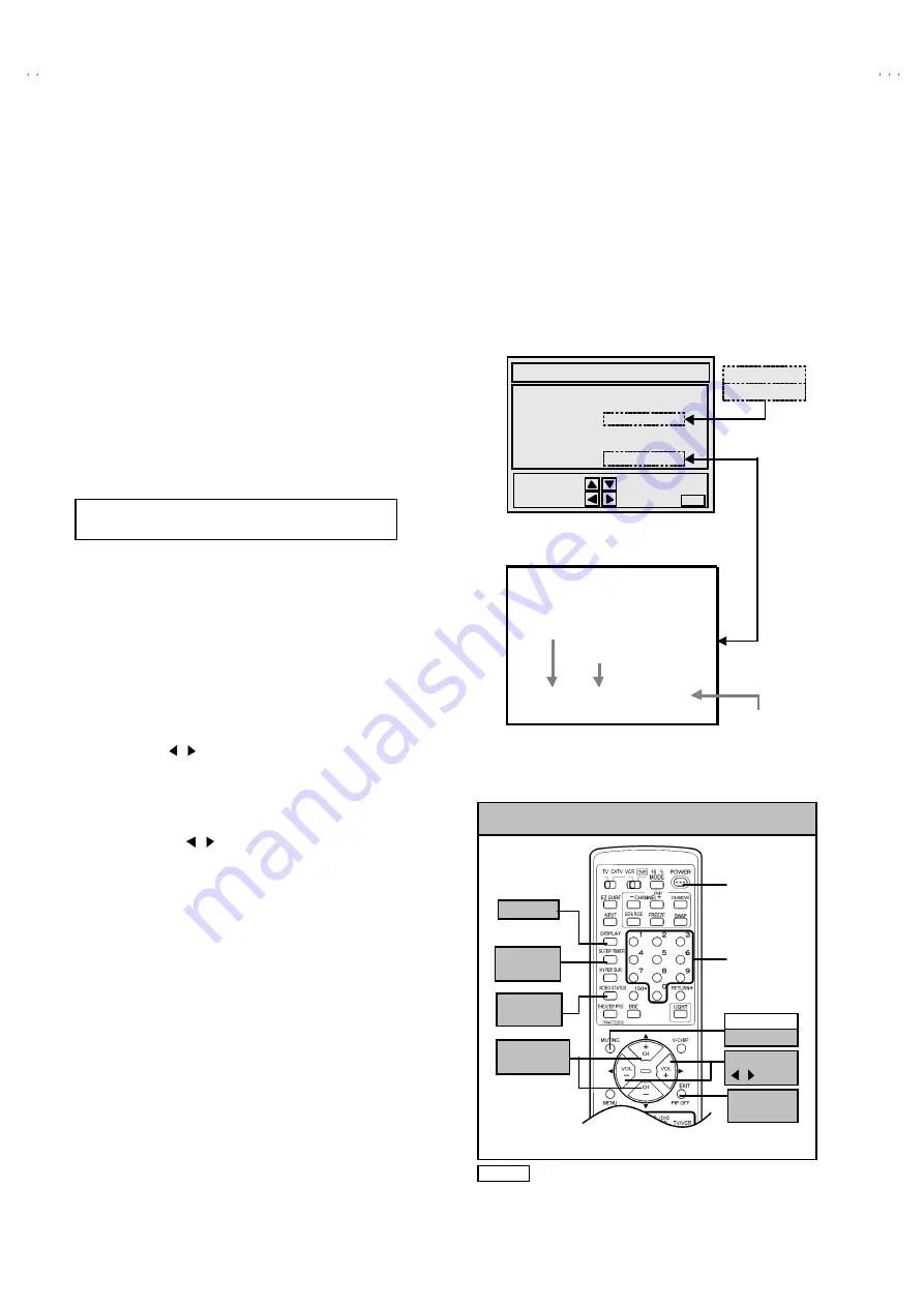
Ho w to enter the SERVICE MENU.
1) Press the
SLEEP TIMER
key of the remote c ontrol unit and set
the
SLEEP TIMER
for
「
0 min
」
.
2) Before dis appear the display of
SLEEP TIMER
settings ,
simultaneously press the
DISPLAY
key and
VIDEO STATUS
key
of the remote control unit.
3) The SERVICE MENU screen will be dis played as shown Fig.1.
Ho w to enter the 12. SYSTEM(SYS).
4)
While the SERVICE MENU is dis played, select the
12.SYSTEM(SYS)
item with FUNCTION (
▼
/
▲
) keys, and the
FUNCTION ( / ) keys is press ed, the screen will be displayed
as s hown in Fig.2.
5) Refer to the SYSTEM ( SYSTEM CONSTANT) TABLE 1 and
check the setting items. If the value is different, select the setting
item with the FUNCTION (
▼
/
▲
) keys and adjust the setting with
the FUNCTION( / ) key s. (The letters of the selected item are
displayed in yellow.)
6) When adjustment has c ompleted, the values store into memory
IC automatically
7) Press the EXIT key to return the SERVICE MENU screen.
8) Then press the EXIT key again to return the normal screen.
(5) Receive the channel setting
Refer to the OPERATING INSTRUCTIONS (USER'S GUIDE) and
set the receive channels (Channels Preset) as desc ribed.
(6) User settings
Check the us er setting items acc ording to TABLE 2.
Where thes e do not agree, refer to the OPERATING
INSTRUCT IONS (USER'S GUIDE) and set the items as described.
(7) SERVICE MENU setting
Verify what to set in the SERVICE MENU, and set whatever is
necessary (Fig.1) .
Refer to the SERVICE ADJUSTMENT for s etting.
12.SYSTEM(SYS)
***
SYS0 1 VIDEO IN
SERVICE MENU
1.V/C(S)
2.DEF(D)
3.SOUND(A)
4.OTHERS(F)
5.PIP(PIP)
6.3L Y/C(LYC)
7.LOW LIGHT
8.HIGH LIGHT
9.RF AFC
10.VCO
11.I
2
C BUS
12.SYSTEM(SYS)
SELECT BY
OPERATE B Y EXIT BY
EXIT
AV-36F803
/Y
6.3D Y/C(DYC)
SETTING ITEM
SETTING ITEM NUMBER
SETTING VALUE
SERVICE MENU
NOTE Although design is different as this figure, each
remote controller has the s ame c ontrol func tion.
Fig.1
Fig.2
KEY ASSIGNMENT OF REMOTE CONTROL UNIT
DISPLAY
(RM-C325G)
FUNCTION
▼
/
▲
POWER
NUMBER
SLEEP
TIMER
VIDEO
STATUS
EXIT
PIP OFF
FUNCTION
/
MUTING
MEMORY


