background image

12

AV-20FD22

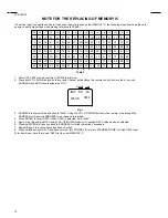
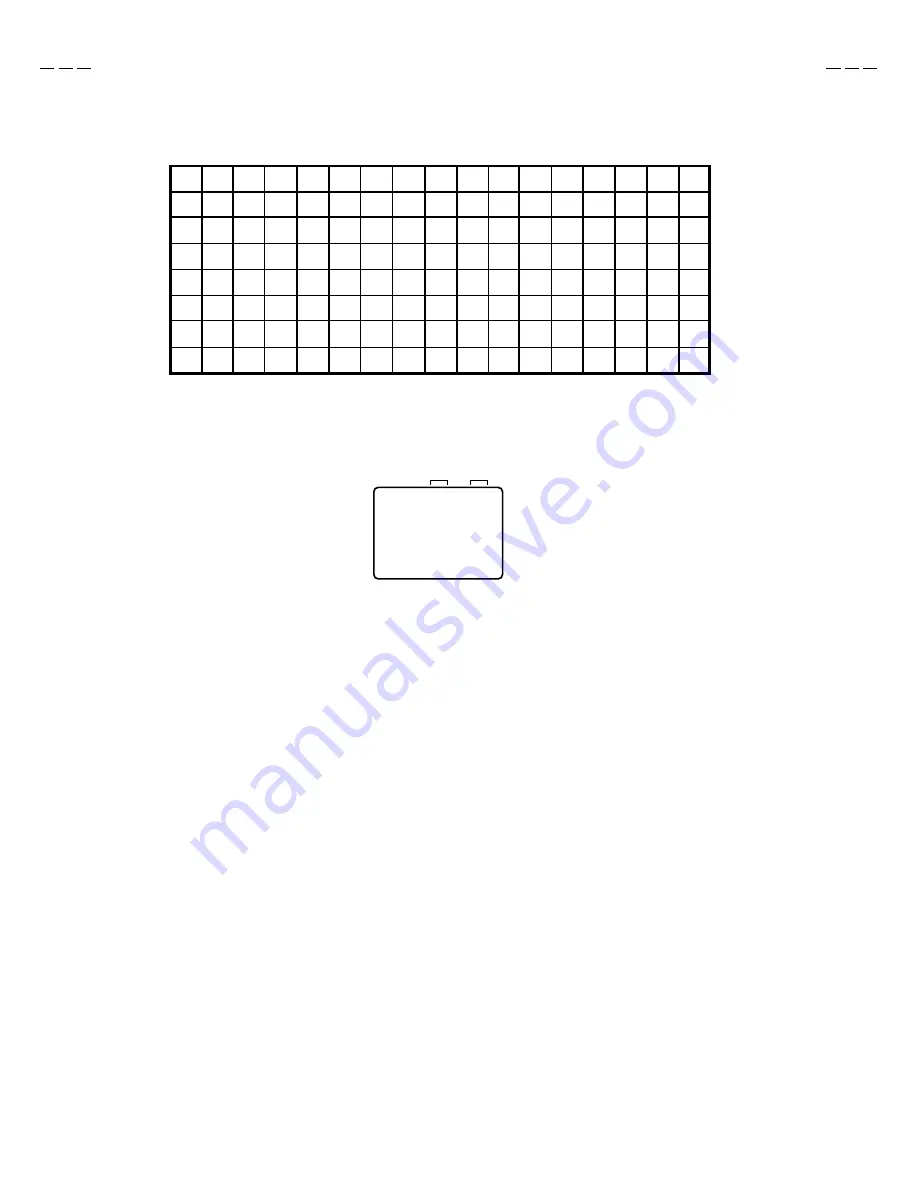
NOTE FOR THE REPLACING OF MEMORY IC

If a service repair is undertaken where it has been required to change the MEMORY IC, the following steps should be taken to
ensure correct data settings while making reference to TABLE 1.

F9

43

05

01

F1

23

27

F7

81

CD

+0

+1

+2

+3

+4

+5

+6

+7

+8

+9

+A

+B

+C

+D

+E

+F

INI

64

67

69

2A

6B

6C

6D

6E

6F

54

74

55

75

75

56

56

76

76

57

78

59

59

79

79

5A

5A

7A

7A

5B

7C

5D

7D

7D

5E

5E

7E

7E

5F

D9

3F

3F

40

61

63

00

10

26

70

71

52

72

53

73

20

57

77

77

58

58

78

30

5B

7B

7B

5C

5C

7C

40

5D

5F

5F

7F

7F

BF

B7

B9

A1

C5

00

C7

00

00

00

97

D9

B0

84

88

9A

9F

2A

5A

00

00

50

AC

AF

7F

A8

B8

B4

7A

60

00

10

---

---

---

---

INIT    00     83

0010

CRT ON

ADDRESS

DATA

3.

4.
5.
6.
7.
8.
The unit will now have the correct DATA for the new MEMORY IC.

Table 1

1.
2.

Fig. 1

Enter DATA SET mode by setting VOLUME to minimum.
Press both VOL. DOWN button on the set and Channel button (6) on the remote control for more than 1 second.
ADDRESS and DATA should appear as FIG 1.

ADDRESS is now selected and should "blink". Using the VOL. UP/DOWN button on the remote, step through the
ADDRESS until required ADDRESS to be changed is reached.
Press ENTER to select DATA. When DATA is selected, it will "blink".
Again, step through the DATA using VOL. UP/DOWN button until required DATA value has been selected.
Pressing ENTER will take you back to ADDRESS for further selection if necessary.
Repeat steps 3 to 6 until all data has been checked.
When satisfied correct DATA has been entered, turn POWER off (return to STANDBY MODE) to finish DATA input.

Summary of Contents for AV-20FD22

Page 1: ...㨯㨯㨯㨯㨯㨯㨯㨯㨯㨯㨯㨯㨯 㨯㨯㨯㨯㨯㨯㨯㨯㨯㨯㨯㨯㨯㨯㨯㨯㨯㨯㨯㨯㨯㨯㨯㨯㨯㨯㨯㨯㨯㨯㨯㨯 㨯㨯㨯㨯㨯㨯㨯㨯㨯㨯㨯㨯㨯㨯㨯㨯㨯 㨯㨯㨯㨯㨯㨯㨯㨯㨯㨯㨯㨯㨯㨯㨯㨯㨯 㨯㨯㨯㨯㨯㨯㨯㨯㨯㨯㨯㨯㨯㨯㨯㨯㨯 㨯㨯㨯㨯㨯㨯㨯㨯㨯㨯㨯㨯㨯㨯㨯㨯㨯7 SERVICE ADJUSTMENTS 㨯㨯㨯㨯㨯㨯㨯㨯㨯㨯㨯㨯㨯㨯㨯㨯㨯㨯㨯㨯㨯㨯㨯㨯㨯㨯㨯㨯㨯㨯㨯㨯 㨯㨯㨯㨯㨯㨯㨯㨯㨯㨯㨯㨯㨯㨯㨯㨯㨯㨯㨯㨯㨯㨯㨯㨯㨯㨯㨯㨯㨯㨯㨯㨯 㨯㨯㨯㨯㨯㨯㨯㨯㨯㨯㨯㨯㨯㨯㨯㨯㨯㨯㨯㨯㨯㨯㨯㨯㨯㨯㨯㨯㨯㨯㨯㨯 㨯㨯㨯㨯㨯㨯㨯㨯㨯㨯㨯㨯㨯㨯㨯㨯㨯㨯㨯㨯㨯㨯㨯㨯㨯㨯㨯㨯㨯㨯㨯㨯 㨯㨯㨯㨯㨯㨯㨯㨯㨯㨯㨯㨯㨯㨯㨯㨯㨯㨯㨯㨯㨯㨯㨯㨯 㨯㨯㨯㨯㨯㨯㨯㨯㨯㨯㨯㨯㨯㨯㨯㨯㨯㨯㨯㨯㨯㨯㨯㨯 㨯㨯㨯㨯㨯㨯㨯㨯㨯㨯㨯㨯㨯㨯㨯㨯㨯㨯㨯㨯㨯㨯㨯㨯 㨯㨯㨯㨯㨯㨯㨯㨯㨯㨯㨯㨯㨯㨯㨯㨯㨯㨯㨯㨯㨯㨯㨯㨯 13 GUIDE FOR REPAIRING 㨯㨯㨯㨯㨯...

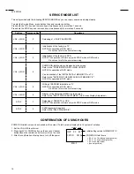
Page 2: ...THE REPLACING OF MEMORY IC NOTE No operation at DVD mode VOL MIN 3 VOL MIN 6 VOL MIN 0 Releasing of V CHIP PASSWORD Writing of EEPROM initial data on TV NOTE No operation at DVD mode Do not use this for the normal servicing VOL MIN 9 Display of the Adjustment MENU on the screen Refer to the ELECTRICAL ADJUSTMENT On Screen Display Adjustment STOP 7 STOP 9 Self Diagnosis will operate Refer to the SE...

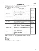
Page 3: ...or appears or Color and Black White bar appears alternately Syscon PCB Power Block 4 TRAY CHECK TRAY OPEN will appear on the TV Monitor Then the tray will be opened completely and TRAY CLOSE will appear Then the tray will be closed Sight check if the tray opens or closes correctly Syscon PCB Drive Unit Power Block 5 EEPROM CHECK EEPROM will appear on the TV Monitor Then non specific data will be r...

Page 4: ...SS DATA 3 4 5 6 7 8 The unit will now have the correct DATA for the new MEMORY IC Table 1 1 2 Fig 1 Enter DATA SET mode by setting VOLUME to minimum Press both VOL DOWN button on the set and Channel button 6 on the remote control for more than 1 second ADDRESS and DATA should appear as FIG 1 ADDRESS is now selected and should blink Using the VOL UP DOWN button on the remote step through the ADDRES...

Page 5: ... 43 44 45 46 47 48 49 50 51 52 53 54 55 56 57 58 59 60 61 62 63 64 65 66 67 68 69 70 71 72 FUNCTION R CUT OFF G CUT OFF B CUT OFF G DRIVE B DRIVE BRIGHTNESS CENT BRIGHTNESS MAX BRIGHTNESS MIN COLOR CENT COLOR MAX COLOR MIN TINT SUB CONTRAST CONTRAST CENT CONTRAST MAX CONTRAST MIN SHARPNESS RGB CONTRAST H POSITION V POSITION V SIZE V LINEARITY V S CORRECTION EW PARABOLA CORR EW TRAPEZIUM CORR H SIZ...

Page 6: ...ect VLIN Press the VOL UP DOWN button on the remote control until the upside and downside screen size of the horizontal line becomes the same 2 9 VERTICAL SHIFT NOTE Adjust after performing adjustments in section 2 8 2 10 VERTICAL SIZE NOTE Adjust after performing adjustments in section 2 9 1 2 3 4 Receive the center cross signal from the Pattern Generator Using the remote control set the brightne...

Page 7: ...th Filter and without Filter should be more than 20dB for both L and R 2 18 SUB BRIGHT CENTER 1 2 3 4 5 6 7 8 9 10 11 12 Receive the monoscope pattern RF Input Using the remote control set the brightness and contrast to normal position Activate the adjustment mode display of Fig 1 1 and press the channel button 06 on the remote control to select BRTC Press the VOL UP DOWN button on the remote cont...

Page 8: ... Using the remote control set the brightness contrast color and tint to normal position Connect the oscilloscop to TP801 Activate the adjustment mode display of Fig 1 1 and press the channel button 09 on the remote control to select COLC Adjust the VOLTS RANGE VARIABLE knob of the oscilloscope until the range between white 100 and 0 is set to 4 scales on the screen of the oscilloscope Press the VO...

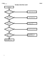
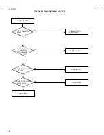
Page 9: ...ltage at pin1 of Q505 DC7 3V NO YES NO YES NO YES NO Q510 Q509 Q503 OK Check Q510 Q509 Q503 and TV POWER H Line Check IC501 and associated circuit When it pushed POWER ON SW as for LED is it lighted Is the voltage at pin34 of IC101 DC4 7V Check Q505 and associated circuit Check IC101 and associated circuit ...

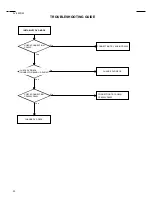
Page 10: ... NO YES NO YES NO Change of T501 Check IC501 and associated circuit and change of Q505 F501 OK Check D501 and associated circuit Is the voltage at pin4 of IC501 DC18V and pin5 2V Change of IC501 YES NO Check I503 and associated circuit Is the voltage at pin1 of IC501 DC16V Is the voltage at pin1 of Q505 DC7 3V ...

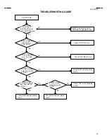
Page 11: ...ES NO YES NO Check SPEAKER HEADPHONE and IC301 CD301 CD302 INSERT OK Check SOUND B Line Is the voltage at pin5 of IC302 DC3 9V Q301 OK Check Q301 and A_MUTE Line YES NO Check MONITER_A_R Line MONITER_A_L Line and associated circuit Check TV POWER H Line and associated circuit Is audio signal input from pin55 of IC601 ...

Page 12: ...sociated circuit YES NO Check CHROMA 5V Line Is VIDEO signal output from pin55 of IC601 Is CHROMA signal input from pin42 47 of IC601 Check IC601 and associated circuit Is VIDEO signal output from pin25 of IC701 NO YES Check Q702 and associated circuit Check IC701 and associated circuit Is the setting of the BRIGHT center and CONTRAST max BRIGHT is adjusted to center CONTRAST is adjusted to max ...

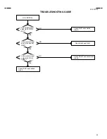
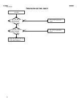
Page 13: ...just the COLOR setting YES Is the receiving of the color signal NO YES NO YES NO Is the setting of the COLOR central Receive the color signal Is the waveform at pin42 of IC601 normal Check X601 associated circuit Check IC601 and associated circuit ...

Page 14: ... YES NO Check R449 and Q401 Check FB401 and associated circuit Check IC601 associated circuit Is the normal signal output to 34PIN of IC601 Check IC601 associated circuit Is the normal signal input in the base of Q405 Is the normal signal output to 9PIN of FB401 ...

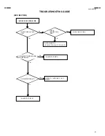
Page 15: ...SD YES NO YES NO Check the pin25 of IC101 and IC601 associatedcircuit Is there the waveform of 22 23 and also 24PIN of IC101 Check IC601 associated circuit Is there the waveform of 20 21 and also 22PIN of IC601 Check IC601 associated circuit ...

Page 16: ... OSD DVD DECK NO OPEN CLOSE CHECK CONNECTION CD811 No CHECK CABLE CD811 Yes CHECK MAIN PCB P CON 5V PCON 9V P CON 5V_D Yes No Yes No REFER TO INSTABILITY DVD MODE DVD MODE STABILITY CHANGE DVD DECK CHANGE DVD DECK DVD SECTION POSSIBLE TO OPEN CLOSE BY MECHANIC ...

Page 17: ...NO PICTURE No Yes No Yes No Yes CHANGE IC8501 CHECK CONNECTION CD4002 CHECK OSILLATION OF X1001 CHANGE DVD DECK No CONNECTION TRY AGAIN CD4002 CHANGE X1001 CHANGE IC4001 CHECK OUTPUT SIGNAL IC8501 49 50PIN CHECK DVD DECK CONNECTOR BEND OR SHORT ...

Page 18: ... Yes No CONNECTION TRY AGAIN CD4001 No WHEN PLAY CHECK THE DECK MOTOR TUCH No CHANGE DVD DECK Yes Yes No CHECK OUTPUT SIGNAL IC8501 8 10 13PIN REFER TO DVD NO PICTURE CHECK THE CIRCUIT AROUND IC701 AFTER READING CHECK INCORRECT DISC DISPLAY CHECK DVD DECK CONNECTOR BEND OR SHORT ...

Page 19: ...DE INSTABILITY DVD MODE No Yes CONNECTION TRY AGAIN CD4002 CHECK CONNECTION CD4002 No Yes CHANGE DVD DECK No Yes CONNECTION TRY AGAIN CP8002 CP8003 CHECK CONNECTION CP8002 CP8003 CHANGE DVD DECK CHECK DVD DECK CONNECTOR BAND OR SHORT ...

Page 20: ...E CD NO PLAY Yes No WHEN READING CHECK THE DECK MOTOR TURN CHANGE DVD DECK Yes No Yes No CHECK CONNECTION CP4002 AROUND THE CIRCUIT CHECK INPUT SIGNAL IC4001 3 5 6PIN CHANGE DVD DECK CHANGE IC4001 CHECK DVD DECK CONNECTOR BEND OR SHORT ...

Page 21: ...LATED NEUTRAL side GND or never measure with a measuring apparatus oscilloscope etc the LIVE side GND and ISOLATED NEUTRAL side GND at the same time If the above precaution is not respected a fuse or any parts will be broken Since the circuit diagram is a standard one the circuit and circuit constants may be subject to change for improvement without any notice CONTENTS SEMICONDUCTOR BASE CONNECTIO...

Page 22: ...140 EIC MTZJ5 6B T 77 MTZJ6 8B T 77 IC OEC6063A MM1311AD BT865AKRF AN5829S BR24C01AF WE2 S 24C08ADPA 01 NJM4580M TB1253N MD36710X CD4053BNSR TC90A45P ZR36703 HY57V161610DTC 8 LA7151M TP T1 M62420FP PCM1716E SN74LV4052APW TRANSISTOR PST600C KIA7805API STR G6624 AN7522 AN5522 2SA1013 TPE6 2SC1740SP TP KIA7809API 2SA1624 AA KRC111MAT 2SB1131 S T AE KRC114MAT 2SC2909 S T AA KTC3198 AT Y GR 2SD1246 S T...

Page 23: ... B D 14 10 19 2 MAIN IC101 OEC6063A 17 18 22 23 24 A 26 27 36 33 3 1 RESET IC102 PST600C AT 5V Q204 BUFFER Q202 Q203 BUFFER VOL DOWN CH DOWN VOL UP CH UP STOP PLAY SKIP FF OPEN CLOSE FROM OPERATION BLOCK 32 31 X101 16MHz SKIP REW TV BLOCK DIAGRAM 5 38 4 37 AV SW IC701 MM1311AD 24 15 8 13 10 23 17 18 B 2 31 30 32 4 7 1 14 Q753 BUFFER 25 Q702 BUFFER SOUND DECORDER IC902 AN5829S 14 19 18 22 21 R V J7...

Page 24: ...LK ALRCLK ASDATA VSYNC HSYNC CLK27 YUVO 7 C B ZERO L R CVBS Y C ANALOGUE AUDIO OUT ANALOGUE YC OUT AUDIO SW IC8504 SN74LV4052APW SPDIF DVD SPDIF CD Q7013 Q7005 LINE DRIVER B A J7002 COAXIAL DIGITAL OUT X1001 12 5MHz B CTRL BUS FROM_SYSCON DVD L CD H DVD CD HD0 7 SYSCON IC1001 ZR36703 SSC FROM_SYSCON SCLK TO_SYSCON ATN HRST TO TV BLOCK RESET RESET TX RX DVD RESET SYS MUTE SCL SDA SCL SDA SCL SDA A ...

Page 25: ...CON 9V DRV Q501 P CON 9V SW Q502 B 130V DRIVE P CON SW Q508 5 6V REG Q150 P CON 5V DRIVER Q153 3 1 5V REG IC154 KIA7805API 3 1 5V REG IC503 KIA7805API P CON 12V DRIVER Q157 P CON 3 3V OUT Q158 Q159 Q160 3 1 5V REG IC152 KIA7805API 3 1 9V REG IC153 KIA7809API F502 P CON SW Q152 P CON 3 3V OUT Q154 Q155 Q156 POWER BLOCK DIAGRAM DEGAUSS_H P CON 3 3V P CON D5V P CON 3 3V_A AT 5 6V AT 8V SOUND B AT 8V ...

Page 26: ...BT 8V FBT 12V X RAY TEST AT 8V CP8502 CP8003 AUDIO R AUDIO L DVD RESET ZERO GND GND GND GND GND GND GND GND CVBS RED GREEN MUTE DVD Y DVD C CVBS 5 5 18 17 16 15 14 13 12 11 10 9 8 7 6 4 3 2 1 18 17 16 15 14 13 12 11 10 9 8 7 6 4 3 2 1 OPERATION PCB TEAA65 PCB030 AT 5V KEY 1 GND REMOCON OUT POWER ON LED CD751 CD403 CP403 1 GND NC NC NC NC FOCUS CP807 SCREEN 1 11 10 9 180V 180V GND GND L503 CLAMP B ...

Page 27: ... HD5 HD4 HD3 HD2 HD1 YUV0 HD0 YUV1 HA4 YUV2 HA3 YUV3 HA2 YUV4 HRST HA1 YUV5 SSC MRST SSC MTSR HWR YUV6 SSC SCLK SSC ATN HD7 HD6 MPGCS YUV7 HD5 HD4 HRD HD3 HD2 HSYNC MA4 HD1 MA3 HD0 VSYNC MA5 HA4 MA2 HA3 MA6 HA2 MA1 HA1 MPGIRQ MA7 HWR MA0 MPGCS MA8 HRD MA10 MPGIRQ MA9 MPGRST MA11 MPGSTBY MCS0 HRDY MRAS MPCLK MCAS MWE MDQM MD8 MD7 MD9 MD6 MD10 MD5 MD11 MD4 MD12 MD3 MD13 MD2 MD14 MD1 MD15 MD0 MA4 MA3...

Page 28: ...A7 MD15 MD0 MA0 MA8 MA10 MD14 MD1 MA9 MA11 MCS0 MRAS MPCLK MCAS MD13 MD2 MWE MDQM MD8 MD12 MD3 MD7 MD9 MD6 MD10 MD5 MD11 MD11 MD4 MD4 MD12 MD3 MD10 MD5 MD13 MD2 MD14 MD1 MD15 MD0 MD9 MD6 MD8 MD7 MDQM MDQM MWE MPCLK MCAS MRAS MCS0 MA9 MA11 MA8 MA10 MA7 MA0 MA6 MA1 MA5 MA2 MA4 MA3 P CON 3 3V SD DGND FROM TO VIDEO ENCORDER SDRAM SCHEMATIC DIAGRAM SYSCON PCB MPEG FROM TO 3 3 NC NC VSS I O15 I O14 VSSQ...

Page 29: ...HD1 SO2 HA1 HD0 HA4 HA3 HA2 HA1 HWR HD7 MPGCS HRD MPGIRQ MPGRST HD6 MPGSTBY HRDY HD5 HD4 HD3 HD2 HD1 HD0 MPGIRQ MPGRST MPGSTBY DVD_RESET RESET MPGCS CD DVD HRD HWR SW1 SYSCON PCB SYSCON SCHEMATIC DIAGRAM NC NC NC NC NC NC NC NC NC FROM TO MPEG FROM TO VIDEO ENCORDER VCC P47 A07 P46 A06 P45 A05 P44 A04 P43 A03 P42 A02 P41 A01 VCC P40 A00 P37 D31 VSS P36 D30 P35 D29 P34 D28 P33 D27 P32 D26 P31 D25 P...

Page 30: ...ND SUBJECT TO CHANGE WITHOUT NOTICE NOTE THIS SCHEMATIC DIAGRAM IS THE LATEST AT THE TIME IC8504 SN74LV4052APW DIGITAL AUDIO SW 1 10 11 12 13 14 15 16 2 3 4 5 6 7 8 9 P CON 3 3VA DGND P CON 3 3V MP P CON 3 3V AMCLK CLK27 SI2 ABCLK ALRCLK SO2 SPDIF DVD SSC MRST ASDAT0 YUV0 YUV0 SSC MTSR YUV1 SW1 YUV2 YUV1 YUV3 DVD_RESET YUV4 YUV2 D_LOAD H YUV5 YUV6 YUV7 YUV3 HSYNC VSYNC YUV4 SPDIF CD DM1 D_LOAD H Y...

Page 31: ...N POINT DE VUE SECURITE ETANT LES PIECES REPAREES PAR UN ATTENTION DESCRIBED IN PARTS LIST ONLY CRITICAL FOR SAFETY USE ONES ARE SINCE THESE PARTS MARKED BY CAUTION DIGITAL AUDIO SIGNAL PB PLAYBACK VIDEO SIGNAL AUDIO SIGNAL PB CAUTION DIGITAL TRANSISTOR PLAYBACK COLOR SIGNAL PLAYBACK LUMINANCE SIGNAL CP8004 51048 1110 1 10 11 2 3 4 5 6 7 8 9 CP8005 51048 1200 1 10 11 12 2 3 4 5 6 7 8 9 L802 W5T29X...

Page 32: ...AST WAS RECEIVED IN GOOD CONDITION AND PICTURE IS NORMAL NOTE OF PRINTING AND SUBJECT TO CHANGE WITHOUT NOTICE NOTE THIS SCHEMATIC DIAGRAM IS THE LATEST AT THE TIME DANS LA NOMENCLATURE DES PIECES N UTILISER QUE CELLS DECRITES DANGEREUSES AN POINT DE VUE SECURITE ETANT LES PIECES REPAREES PAR UN ATTENTION DESCRIBED IN PARTS LIST ONLY CRITICAL FOR SAFETY USE ONES ARE SINCE THESE PARTS MARKED BY CAU...

Page 33: ...KA C634 47 16V YK C620 100 10V YK C608 1 50V KA C641 2 2 50V KA Q204 2SC2412K EXT AUDIO DRV Q205 2SC2814 PRE AMP Q608 2SC2412K VD SW Q203 2SC2412K T V BUF Q202 2SC2412K CLAMP Q603 2SC2412K SW Q604 2SC2412K BUFFER W871 W818 W849 W848 W861 THE DC VOLTAGE AT EACH PART WAS MEASURED WITH THE DIGITAL TESTER WHEN THE COLOR BROADCAST WAS RECEIVED IN GOOD CONDITION AND PICTURE IS NORMAL NOTE OF PRINTING AN...

Page 34: ... 100 R304 10K R302 68K R313 1K R317 8 2K R319 1001 4W R318 100 1 4W R346 100K1 4W R301 3 3K R320 100K 1 4W C346 2 2 50V KA C327 2 2 50V KA C305 100 16V YK C301 100 16V YK C328 4 7 50V KA C347 2 2 50V KA C319 2 2 50V KA Q301 2SC2412K MUTE Q304 2SC2412K MUTE Q303 2SC2412K MUTE W845 THE DC VOLTAGE AT EACH PART WAS MEASURED WITH THE DIGITAL TESTER WHEN THE COLOR BROADCAST WAS RECEIVED IN GOOD CONDITIO...

Page 35: ...K R7039 1K R7042 120 R7041 120 1 4W R7046 22K R7027 10K R7050 681 4W R7049 330 1 2W R7048 12K R7047 100 R7053 2201 2W R7043 10K R7056 120K R7057 180K R7059 180K R7058 120K R7060 2 2K R7062 2 2K R7061 751 4W R7055 1K 1 4W R7054 1K R7025 2 2K R7026 2 2K C7031 22 16V KA C7032 22 16V KA C7030 2 2 50V KA C7014 33 10V KA C7007 2 2 50V KA C7006 2 2 50V KA C7013 10 16V KA C7011 4 7 50V KA C7017 470 16V YK...

Page 36: ...8008 10 50V YK C8007 10 50V YK C717 2 2 50V KA C716 2 2 50V KA C715 2 2 50V KA C729 2 2 50V KA C730 2 2 50V KA C704 2 2 50V KA C705 2 2 50V KA Q8003 2SC2412K BUFFER Q8002 2SC2412K BUFFER Q702 2SC2412K BUFFER W834 W824 W853 W873 W825 OF PRINTING AND SUBJECT TO CHANGE WITHOUT NOTICE NOTE THIS SCHEMATIC DIAGRAM IS THE LATEST AT THE TIME PLAYBACK VIDEO SIGNAL AUDIO SIGNAL PB GND P CON 9V DVD_VIDEO SWD...

Page 37: ...R755 820 R757 680 R760 1K1 4W R761 1K R753 6 8K R773 6 8K R751 100 R752 1001 4W R756 820 R775 820 R763 2 2K R762 100 C775 220 6 3V KA Q751 2SC2412K BUFFER Q754 2SC2412K BUFFER W858 W863 W831 W830 W832 W829 THE DC VOLTAGE AT EACH PART WAS MEASURED WITH THE DIGITAL TESTER WHEN THE COLOR BROADCAST WAS RECEIVED IN GOOD CONDITION AND PICTURE IS NORMAL NOTE OF PRINTING AND SUBJECT TO CHANGE WITHOUT NOTI...

Page 38: ...L TESTER WHEN THE COLOR BROADCAST WAS RECEIVED IN GOOD CONDITION AND PICTURE IS NORMAL NOTE OF PRINTING AND SUBJECT TO CHANGE WITHOUT NOTICE NOTE THIS SCHEMATIC DIAGRAM IS THE LATEST AT THE TIME SCL SDA TUNER_A_L TUNER_A_R TU_AUDIO P CON A5V GND AV PCB STEREO SCHEMATIC DIAGRAM NC 2 3 Filter SAPout 75us De Emph Switch L R SAP DAC Expand Wide Band Cancel Offset Cancel Offset Matrix AGC OUT SW 0 0 3 ...

Page 39: ... SW752 SKHVBED010 OPEN CLOSE SW753 SKHVBED010 STOP SW755 SKHVBED010 SKIP FF SW756 SKHVBED010 SKIP REW GND B Vout OS751 PIC 28143TC5 1 2 3 C751 47 16V KA THE DC VOLTAGE AT EACH PART WAS MEASURED WITH THE DIGITAL TESTER WHEN THE COLOR BROADCAST WAS RECEIVED IN GOOD CONDITION AND PICTURE IS NORMAL NOTE OF PRINTING AND SUBJECT TO CHANGE WITHOUT NOTICE NOTE THIS SCHEMATIC DIAGRAM IS THE LATEST AT THE T...

Page 40: ...63WSA0017 R542 0 15 1W R505 33K 3W R501 1 2 7W CP502 TV 50P 02 A1 1 2 F502 2 5A125V 51MS025LCC F501 6 3A125V 51MS063LCC FH504 EYF 52BC FH503 EYF 52BC FH502 EYF 52BC FH501 EYF 52BC RY501 ALKS321 1 2 3 4 2 1 L503 DEGAUSS COIL L501 SS28H 20075 1 2 3 4 R529 2 7K 1 4W 1 D519 10ELS2N D521 1SS133 ICP501 20N_4000FS 4A 125V ICP502 20N_4000FS 4A 125V ICP504 20N_4000FS 4A 125V IS THE LIVE CONNECTION CAUTION ...

Page 41: ...1 25KV MPP C423 0 47 250V PMS C424_1 680P 2KV YR C409 0 0022 M C429_1 470P 500V B C432 0 1 100V MKT C450 0 001 2KV YR C412 56P 500V SL C405_1 3 3 50V MHE C418 1 160V MHE C407 2200 25V MHE C421 1000 35V MHE C403 10 50V YK C433 22 100V MHE OF PRINTING AND SUBJECT TO CHANGE WITHOUT NOTICE NOTE THIS SCHEMATIC DIAGRAM IS THE LATEST AT THE TIME DESCRIBED IN PARTS LIST ONLY CRITICAL FOR SAFETY USE ONES A...

Page 42: ...804 220 1 4W R808 2 7K 1 4W C819 0 0022 2KV B C809 390P B C810 270P B C811 270P B OF PRINTING AND SUBJECT TO CHANGE WITHOUT NOTICE NOTE THIS SCHEMATIC DIAGRAM IS THE LATEST AT THE TIME DESCRIBED IN PARTS LIST ONLY CRITICAL FOR SAFETY USE ONES ARE SINCE THESE PARTS MARKED BY CAUTION DANS LA NOMENCLATURE DES PIECES N UTILISER QUE CELLS DECRITES DANGEREUSES AN POINT DE VUE SECURITE ETANT LES PIECES R...

Page 43: ... corresponding balloon number in the schematic diagram NOTE 1 2 3 4 5 SDRAM VIDEO ENCODER 7 6 9 10 11 MICON TUNER 22 23 24 25 12 The following waveforms were measured at the point of the corresponding balloon number in the schematic diagram VIF SIF CHROMA SOUND AMP IN OUT 21 26 27 28 29 NOTE 30 31 32 33 34 35 36 38 39 37 ...

Page 44: ...nctions Front STOP button Rear AC power cord PLAY button OPEN CLOSE button Disc tray POWER button AUDIO L R VIDEO OUT jacks SERVICE jack COAXIAL DIGITAL AUDIO OUT jack AUDIO L R VIDEO IN jacks LINE 1 RF IN jack Headphone Jack CHANNEL buttons VOLUME buttons AUDIO L R VIDEO IN jacks LINE 2 Power indicator Remote sensor HOW TO OPEN THE FRONT DOOR PREVIOUS button NEXT button ...

Page 45: ... of TV setup 13 17 22 24 DVD SETUP Display menu of DVD setup 26 35 36 38 42 SELECT ENTER Enter information in the menu 13 19 21 26 Select option in the menu 27 29 31 34 42 PREV NEXT Skip chapter to forward or reverse direction 28 TV DVD Switch between the TV mode DVD mode 10 26 DVD MENU Display menu of DVD software 34 B SEARCH F SEARCH Fast Forward Review playback 28 PLAY Playback 27 28 31 34 OPEN...

Page 46: ... the screen when you press the MENU button initially Select the language you prefer first then proceed with the other menu options Press TV MENU The TV menu screen will appear Press TV MENU until the MENU screen is cleared Press or to select the LANGUAGE option then press or button 1 2 3 Press or until the SET UP menu appears To turn on the TV DVD press POWER The Power indicator will light If the ...

Page 47: ...the TV CATV menu option is in the CATV position channels can be selected as follows TO SELECT CATV CHANNELS 1 9 Press 0 twice then 1 9 as needed Example to select channel 2 press 002 10 12 Press 0 then the remaining 2 digits Example to select channel 12 press 012 13 99 Press the 2 digits in order Example to select channel 36 press 36 100 125 Press the 3 digits in order Example to select channel 12...

Page 48: ...18 To memorize channels TV RETURN This button allows you to go back to the last channel selected by pressing TV RETURN Press TV RETURN again to return to the last channel you were watching SLEEP TIMER To set the TV DVD to turn off after a preset amount of time press SLEEP TIMER on the remote control The clock will count down 10 minutes for each press of SLEEP TIMER 120 110 10 0 After the sleep tim...

Page 49: ...ined describe titles words in foreign languages or words requiring emphasis Words that are sung usually appear enclosed by musical notes For television programs broadcasting with Closed Captions look in your TV guide for the Closed Captions symbol CC When selecting Closed Captions the captioning will be delayed approximately 10 seconds If no caption signal is received no captions will appear but t...

Page 50: ... menu appears This TV DVD is equipped with a channel memory feature which allows channels to skip up or down to the next channel set into memory skipping over unwanted channels Before selecting channels they must be pro grammed into the TV DVD s memory In addition to normal VHF and UHF channels this TV DVD can receive up to 113 Cable TV channels To use this TV DVD with an antenna set the TV CATV m...

Page 51: ... AUTO CH MEMORY MENU TV CATV ADD DELETE CATV ADD AUTO CH MEMORY MENU TV CATV ADD DELETE CATV ADD AUTO CH MEMORY Press TV MENU in the TV mode The TV menu screen will appear Press or until CHANNEL SETUP menu appears AUTOMATIC MEMORY TUNING Press or to select the AUTO CH MEMORY then press or The TV will begin memorizing all the channels available in your area Press TV MENU until the MENU screen is cl...

Page 52: ...menu screen will appear Enter the password 4 digits using Direct Channel Selection 0 9 then press ENTER Enter the same password again for the safety then press ENTER Now the password was registered and V Chip setting menu will appear on the display NOTES TO REGISTER PASSWORD An age limitation can be set to forbid children to see and hear violent scenes or pictures for adults etc The TV DVD corresp...

Page 53: ...ce suggested NC 17 17 years old and above X Adult only Press or to select the CAN ENG RATING then press or to select desired rating To use after the TV is protected When the program applied to the V Chip setting is received enter the password Protection can be can celled 4 E Exempt Exempt programming includes news sports documentaries and other information program ming talk shows music videos and ...

Page 54: ...LANGUAGE IDIOMA LANGUE TO CHANGE PASSWORD Press TV MENU in the TV mode The TV menu screen will appear Press or until SETUP menu appears Press or to select the V CHIP SET then press or Press or to select CHANGE PASSWORD then press or Enter the new password using Direct Channel Selection 0 9 then press ENTER Enter the same password again for safety then press ENTER Press TV MENU repeatedly to return...

Page 55: ...tory Press or to select the item you want to adjust 1 2 3 4 Press or to adjust the setting 5 After your desired setting press TV MENU until the MENU screen is cleared BRIGHTNESS CONTRAST COLOR TINT SHARPNESS increase brightness increase contrast be brilliant color be greenish color decrease brightness decrease contrast be pale color be reddish color makes picture softer makes picture clearer POWER...

Page 56: ...e control to change to mono sound The noise should be eliminated Press it again to return to the stereo sound LISTENING TO SAP SEPARATE AUDIO PROGRAM TO SELECT DESIRED SOUND MONO SAP BROADCASTING SAP SOUND MONO SOUND MAIN STEREO SOUND MAIN MONO SAP SOUND MONO STEREO SAP BROADCASTING MONO SAP SOUND MAIN MONO SOUND MAIN SAP SOUND Stereo and separate audio program SAP STEREO SAP CH 013 STEREO CH 013 ...

Page 57: ...ment Sound controls are factory preset but you can adjust them individually as follows BASS Press or to adjust the bass sound TREBLE Press or to adjust the treble sound BALANCE Press or to obtain an equal sound level from both speakers Press or until the AUDIO menu appears Press TV MENU in the TV mode The TV menu screen will appear Press or to select the item you want to adjust 1 2 3 4 Press or to...

Page 58: ... the tracks Removing Disc from Case Be sure to hold the edge of disc Do not touch the surface of the disc Pick up the disc gently from the case Do not scratch the disc Do not get dirt on the surface of the disc Do not stick a label or adhesive tape on the disc Do not drop or bend the disc Storing Disc Store the disc in the case to avoid risk of scratches dirt or damage Do not leave disc exposed to...

Page 59: ...t Note When connecting to other equipment unplug the unit from the AC outlet Press POWER on the unit or on the remote control to turn on the unit The POWER indicator will light When using an amplifier switch on the amplifier Press and then press or to select desired language e g English then press ENTER 2 Press DVD SETUP in the stop mode NOTE To make SETUP screen disappear press DVD SETUP or RETUR...

Page 60: ... the stopped point 5 To stop the playback press STOP Then press OPEN CLOSE on the unit The disc tray opens Remove the disc and press OPEN CLOSE on the unit then press POWER The disc tray closes automatically and unit turns off Note If a non compatible disc is loaded Incor rect Disc Region Code Error or Paren tal Error will appear on the TV screen ac cording to the type of loaded disc In this case ...

Page 61: ...AY Press PAUSE during still playback One frame is advanced each time you press PAUSE Frame Advance To resume normal playback press PLAY To resume the still playback press PAUSE Press SLOW Reverse or SLOW Forward during normal playback or still playback Each press of SLOW will change the speed of the slow x1 2 x1 4 x1 6 x1 7 Slow motion Playback To resume normal playback press PLAY Locating a chapt...

Page 62: ...back in the zoom mode However you cannot zoom in during the Slow or Search playback Zooming This unit will allow you to zoom in on the frame image You can then make selections by switching the position of the frame In the zoom mode press ZOOM repeatedly to return to a 1 1 view Off 1 Press ZOOM during play back The centre part of the image will be zoomed in Each press of ZOOM will change the ZOOM 1...

Page 63: ...the A B Repeat Playback the ANGLE feature will not operate You may not be able to set A B Repeat depending on the scenes of the DVD A B repeat does not work with an inter active DVD Repeat playback Press PLAY MODE during playback or stop mode Press PLAY MODE again to make the screen disappear Press PLAY to start Repeat playback To resume normal playback select Repeat Off Title Chapter Track Playba...

Page 64: ... to select Play Mode then press to select program 3 Press or to selecttheprogrammingpo sition UseNumberedbut tons 0 9 toinputtheTrack numbers To program others re peat Step 3 4 Press or to select Program Playback and press ENTER The programmes you se lected will start to playback in the order To return to normal play back selectPlayMode Off To cancel program play select Quit and press ENTER The pr...

Page 65: ...anguage You can select the language when you play a multilingual disc 1 Press AUDIO during play back 2 Note If the desired language is not heard after pressing the button several times the language is not recorded on the disc Changing soundtrack language is can celled when you open the disc tray or turn the power off The initial default lan guage or available language will be heard if the disc is ...

Page 66: ... is cancelled when you open the disc tray or turn the power off Depending on the DVD you may not be able to turn the subtitles on even if they are recorded on it Depending on the DVD you may not be able to turn the subtitles off Depending on the DVD you may not be able to change the subtitles even if multilingual subtitles are recorded on it While playing the DVD the subtitle may change when you o...

Page 67: ...k of the selected title will start 1 Press TITLE during playback Title menu appears on the screen 2 Press or to select the desired title 3 Title Selection Some DVDs allow you to select the disc contents using the menu When you play back these DVDs you can select the sub title language and sound track language etc using the DVD menu Press ENTER The menu continues to another screen Repeat steps 2 an...

Page 68: ...n press or until the level you re quire appears Level 1 DVD software for adults cannot be played back Level 8 All DVD software can be played back Select from the level 1 to level 8 The limitation will be more severe as the level number is lower Press DVD SETUP or RETURN to remove the parental control screen Note Ifeachsetup P 35 42 hasbeen com pleted theunitcanalwaysbeworked under the same conditi...

Page 69: ...re Parental Other To change the parental level Press number buttons 0 9 to enter the password you have stored 1 Press DVD SETUP in the stop mode or No Disc Press or to select Parental Then press or ENTER 2 Press ENTER The rating is now unlocked 3 Note Do not forget the password If you forget the password contact the dealer that you purchased the unit from Password Parental 5 Enter Setup Return Lan...

Page 70: ... setting screen will disappear Press OPEN CLOSE to remove the disc 1 Load a DVD disc and press PLAY or OPEN CLOSE on the unit see P 27 2 IftheDVDdischasbeendesignedtotemporarilycancelthe Rating level the screen which follows the Reading screen willchange dependingonwhichdiscisplayed Ifyouselect YES with the SELECT key Your disc exceeds The parental control level screen will then appear 3 Enter the...

Page 71: ...s or to select Picture 3 To make SETUP screen disappear press DVD SETUP or RETURN while the SETUP screen is being displayed 4 Note If the DVD disc is not formatted in the pan scan style it displays 4 3 style You can select the aspect ratio for your TV 4 3 Select this mode when connecting to a conventional TV When playing back a wide screen DVD disc it displays the wide picture with black bands at ...

Page 72: ... or ENTER to select ON or OFF 1 Press DVD SETUP in the stop mode or No Disc 2 Press or to select Picture 3 To make SETUP screen disappear press DVD SETUP or RETURN while the SETUP screen is being displayed 4 On screen display can be switched on or off when you press the buttons ON On screen displays appear when you press the buttons factory setting OFF On screen displays do not appear when you pre...

Page 73: ...ubtitle Audio English English English English Francais Espanol Other Enter Setup Return 0 9 Cancel Language Picture Parental Other Setting menu language Press or ENTER Press or to select your desired language then press ENTER 1 Press DVD SETUP in the stop mode or No Disc 2 Press or to select Language 3 To make SETUP screen disappear press DVD SETUP or RETURN while the SETUP screen is being display...

Page 74: ... Francais Espanol The subtitle is displayed with the selected language if it is recorded on the disc Setting subtitle language Press or ENTER Press or to select your desired language then press ENTER 1 Press DVD SETUP in the stop mode or No Disc 2 Press or to select Language 3 To make SETUP screen disappear press DVD SETUP or RETURN while the SETUP screen is being displayed 4 Note If the selected ...

Page 75: ...isc 2 Press or to select Language 3 To make SETUP screen disappear press DVD SETUP or RETURN while the SETUP screen is being displayed 4 Note If the selected language is not recorded on the disc the original language will be heard The same audio soundtrack language can always be selected by your unit even if you replace the disc or turn the power off English Francais Espanol The language you have ...

Page 76: ...1436 Hindi 1819 Norwegian 2425 Thai 3018 Bihari 1218 Hungarian 1831 Oriya 2528 Tibetan 1225 Breton 1228 Icelandic 1929 Panjabi 2611 Tigrinya 3019 Bulgarian 1217 Indonesian 1924 Pashto Pushto 2629 Tonga 3025 Burmese 2335 Interlingua 1911 Persian 1611 Turkish 3028 Byelorussian 1215 Irish 1711 Polish 2622 Turkmen 3021 Cambodian 2123 Italian 1930 Portuguese 2630 Twi 3033 Catalan 1311 Japanese 2011 Que...

Page 77: ...he model and features of each component Check the Owner s Manual provided with each component for the location of video and audio inputs and outputs To Audio L Input To Audio R Input AUDIO cord not supplied Amplifier Rear of TV DVD Audio R Output Audio L Output NOTE When you make the connections above do not set DOLBY DIGITAL to DOLBY DIGITAL MPEG to MPEG to ON on the AV Amplifier If you do a loud...

Page 78: ...er To playback from the camcorder connect the camcorder to the TV DVD as shown 3 To connect the TV to a TV Game VIDEO L MONO AUDIO R LINE 2 IN Front of TV DVD Audio Video cord not supplied To Audio Video OUT VIDEO IN AUDIO IN L AUDIO IN R UHF VHF OUT LINE 1 IN VIDEO L R MONO DIGITAL AUDIO COAXIAL AUDIO VCR VIDEO IN AUDIO IN L AUDIO IN R Rear of TV DVD To Audio Video OUT LINE 1 NOTE In the DVD mode...

Page 79: ...na Check for sources of possible interference Picture wobbles or drifts Station or CATV experiencing problems tune to another station Make sure channels are set into memory CATV company is scrambling signal Check antenna orientation No CATV reception Check all CATV connections Set TV CATV menu option to the CATV mode Station or CATV system problems try another station Make sure TV CATV menu option...

Page 80: ...playback search slow motion play repeat play or program play etc cannot be performed Some discs may not do some of the functions No 4 3 16 9 picture The setup does not match your TV No on screen display Select Display On No surround sound The setup does not match your stereo system The remote control does not function Aim at the remote control at the remote sensor Operate within Approx 5 Meters or...

Page 81: ...ools and appliances such as drills or hair dryers SNOW If the TV VCR is located far from the TV station in a fringe reception area where the signal is weak small dots may appear in the picture If the signal is extremely weak the installation of a larger external antenna may be necessary RADIO FREQUENCY INTERFERENCE RFI Caused by two way radios this type of interference produces moving ripples or d...

Page 82: ...hes 515 mm Depth 19 1 8 inches 483 mm Type 20 508 mm diagonal Quartz PLL Frequency Synthesized VHF 2 13 UHF 14 69 CATV 14 36 A W 37 59 AA WW 60 85 AAA ZZZ 86 94 86 94 95 99 A 5 A 1 100 125 100 125 01 5A VHF UHF In 75 ohm coaxial 3 76 mm 8 ohm x 2 2 5W 2 5W NTSC 1 DVD 12cm 8cm 2 CD 12cm 8cm DVD 4Hz 22KHz CD 4Hz 20KHz 90dB 0 01 Below Measurable Level 96dB Inputs Video RCA 1 Vp p 75ohm Audio RCA 8 dB...

Page 83: ...te Search Codes Function 1 Slide the 2 Way Mode Selector switch to CATV 2 Press the TV POWER and TV RETURN buttons Hold for at least three seconds and release 3 Press TV POWER see if the CATV or Satellite box responds 4 If there was a response press TV RETURN The operating codes are now set If there was no response repeat Step 3 If you repeat Step 3 a total of 52 times without a response use the r...

Page 84: ...51 MEMO ...
Page 85: ...Printed in Thailand 5870201A 01 03 K JVC COMPANY OF AMERICA Division of U S JVC CORP 1700 Valley Road Wayne New Jersey 07470 JVC CANADA INC 21 Finchdene Square Scarborough Ontario Canada M1X 1A7 ...

Reviews: