background image

Master Page: Left-start

22


EN

DIGIT

A

STILL CAMERA (

D

.S.C.) PL

A

Y

B

A

CK

D.S.C. PLAYBACK

You can view the stored images in the memory card, 
one at a time, much like flipping through a photo 
album.

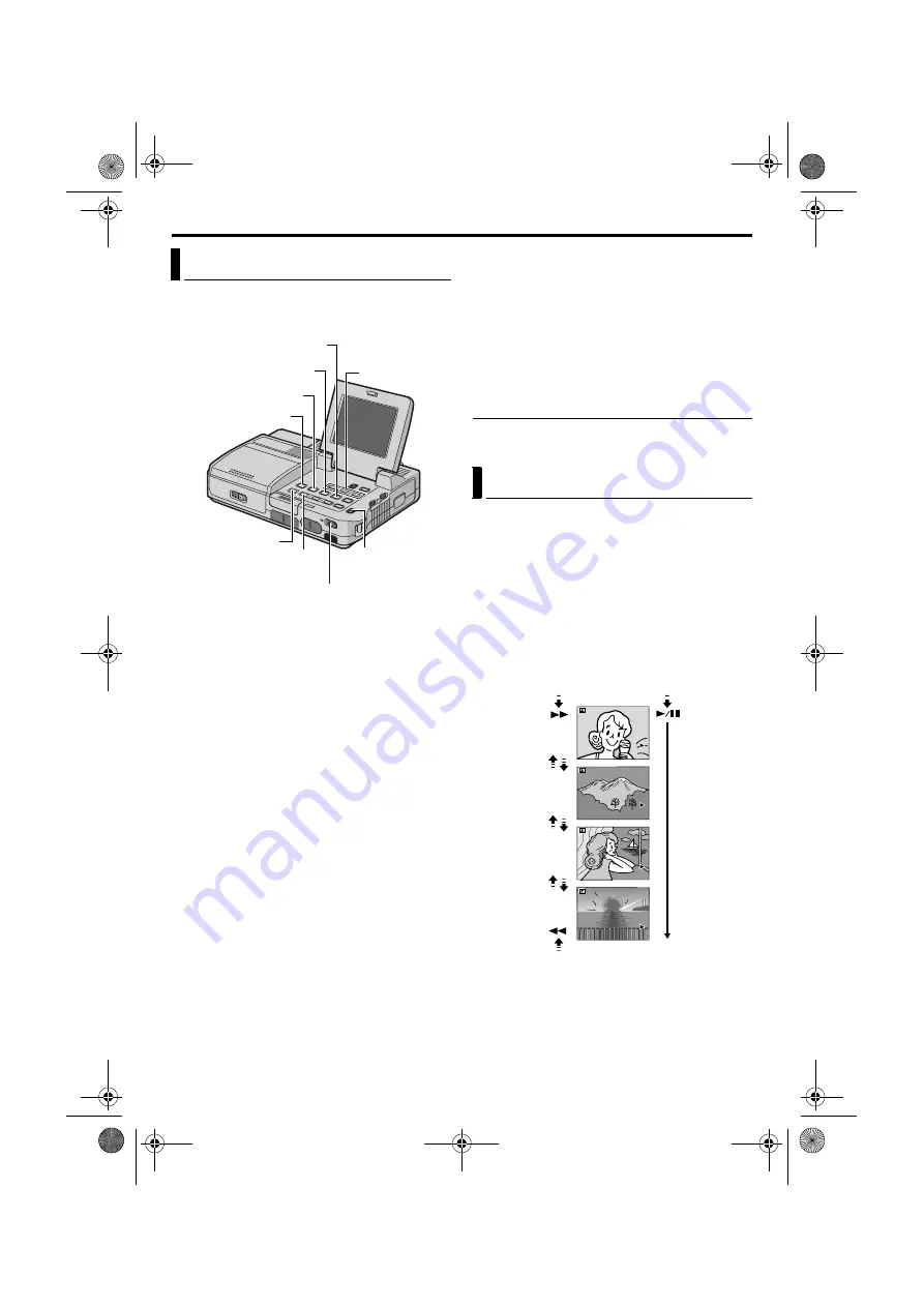
1

Open the LCD monitor fully.

Set the Video Output Mode Switch to “LCD 
MONITOR”. (

pg. 13)

2

Load a memory card. (

pg. 17)

3

Set the Playback Mode Switch to “MEMORY”.

4

Set the Power Switch to “ON” while pressing 
down the Lock Button located on the switch.

The still image which has been played back at 
the last time is displayed.

5

Press 

3

 to display the previous file. Press 

5


to display the next file.

Pressing 

INFO

 gives you details on the 

displayed file. (

pg. 23)

You can also look for the desired file using 
Index Screen. (

pg. 23)

You can turn off the on-screen playback 
display. (

pg. 23)

NOTES:

Images shot in a file size other than “640 x 480”, 
“848 x 480”, “1280 x 720” and “1280 x 960” 
with another devices will be displayed thumbnail 
images. These thumbnail images cannot be 
transferred to a PC.

Images shot with devices (such as JVC GR-
DVM70) that are not compatible with DCF cannot 
be viewed with this player; “UNSUPPORTED 
FILE!” will be displayed.

Playback Zoom

Available only with the remote control (provided). 
(

pg. 41)

You can run through all the images stored in 
memory card automatically.

1

Perform steps 

1

4

 in “Normal Playback Of 

Images”.

2

Press 

4

/

9

 to start Auto Playback. Files are 

displayed in descending order.

If you press 

3

 during Auto Playback, files 

are displayed in ascending order.

3

To end Auto Playback, press 

8

.

Normal Playback Of Images

INFO Button

Play/Pause Button (

4

/

9

)

Rewind Button (

3

)

Playback Mode 

Switch

Power Switch

Stop Button (

8

)

Fast-Forward Button (

5

)

INDEX Button

MENU Button/

R


T

 Button

Auto Playback Of Images

[For Normal Playback]

To display the next image

[For Auto Playback]

Image playback screen

To display the previous image

100-0013

100-0014

100-0015

100-0016

CU-VH1US.book  Page 22  Friday, November 28, 2003  8:01 PM

Summary of Contents for 1203-FOH-ID-VP

Page 1: ...omepage on the World Wide Web for Digital Video Camera For Accessories http www jvc co jp english cyber http www jvc co jp english accessory INSTRUCTIONS For Customer Use Enter below the Model No and Serial No which is located on the bottom of the player Retain this information for future reference Model No Serial No DIGITAL HD PLAYER CU VH1US book Page 1 Friday November 28 2003 8 01 PM ...

Page 2: ... PREVENT FIRE OR SHOCK HAZARD DO NOT EXPOSE THIS UNIT TO RAIN OR MOISTURE CAUTION RISK OF ELECTRIC SHOCK DO NOT OPEN CAUTION TO REDUCE THE RISK OF ELECTRIC SHOCK DO NOT REMOVE COVER OR BACK NO USER SERVICEABLE PARTS INSIDE REFER SERVICING TO QUALIFIED SERVICE PERSONNEL The lightning flash with arrowhead symbol within an equilateral triangle is intended to alert the user to the presence of uninsula...

Page 3: ... these batteries must be followed strictly The apparatus shall not be exposed to dripping or splashing Do not use this equipment in a bathroom or places with water Also do not place any containers filled with water or liquids such as cosmetics or medicines flower vases potted plants cups etc on top of this unit If water or liquid is allowed to enter this equipment fire or electric shock may be cau...

Page 4: ...lar attention to cords at plugs convenience receptacles and the point where they exit from the product 5 Ventilation Slots and openings in the cabinet are provided for ventilation To ensure reliable operation of the product and to protect it from overheating these openings must not be blocked or covered Do not block the openings by placing the product on a bed sofa rug or other similar surface Do ...

Page 5: ...s that produce heat SERVICING 1 Servicing If your product is not operating correctly or exhibits a marked change in performance and you are unable to restore normal operation by following the detailed procedure in its operating instructions do not attempt to service it yourself as opening or removing covers may expose you to dangerous voltage or other hazards Refer all servicing to qualified servi...

Page 6: ...s tripping on the cables will cause the player to fall resulting in damage 䡲 This player is designed exclusively for the digital video cassette SD Memory Card and MultiMediaCard Only cassettes marked and memory cards marked or can be used with this unit Before using the player make sure you only use cassettes with the Mini DV mark make sure you only use memory cards with the mark or remember that ...

Page 7: ... Cable RCA plug to RCA plug S Video Cable Component Video Cable USB Cable Audio Cable x 2 for connection of optional headphones and external microphone 墌 pg 9 Shoulder Strap 墌 pg 9 for attachment RCA BNC Adapter x 3 Remote Control Unit RM V718U Lithium Battery CR2025 for remote control unit A lithium battery is pre installed in the Remote Control Unit at time of shipment with insulation sheet To u...

Page 8: ...ce 1 Release the stoppers on both ends of the core filter 2 Run the cable through the core filter leaving approx 3 cm of cable between the cable plug and the core filter Wind the cable once around the outside of the core filter as shown in the illustration Wind the cable so that it is not slack 3 Close the core filter until it clicks shut NOTES Take care not to damage the cable When connecting a c...

Page 9: ...h The Connector Cover To protect the connectors attach the provided connector cover to the rear panel of the player when the player is not in use How To Use The Audio Cable When using optional headphones or external microphone connect to the provided audio cable with a core filter attached then connect the audio cable to the player The core filter reduces interference Eyelet b Eyelet a Buckle Stra...

Page 10: ...24 Deleting Files 25 Resetting The File Name 26 Setting Print Information DPOF Setting 26 Initializing A Memory Card 27 ADVANCED FEATURES 28 MENUS FOR DETAILED ADJUSTMENT 28 Changing The Menu Settings 28 PLAYBACK MENUS 29 NAVIGATION 32 NAVIGATION Function 32 DUBBING 34 Dubbing To Or From A VCR 34 Dubbing To Or From A Video Unit Equipped With An i LINK Connector Digital Dubbing 35 Recording From Th...

Page 11: ...r may not light In this case remove the battery pack from the AC Power Adapter Charger then try charging again If the battery operation time remains extremely short even after having been fully charged the battery is worn out and needs to be replaced Please purchase a new one For other notes 墌 pg 44 Using The Battery Pack 1 With the arrow on the battery pack pointing to the left push the battery p...

Page 12: ...etals as this can result in a short circuit and possibly start a fire The Benefits Of Lithium Ion Batteries Lithium ion battery packs are small but have a large power capacity However when one is exposed to cold temperatures below 10 C 50 F its usage time becomes shorter and it may cease to function If this happens place the battery pack in your pocket or other warm protected place for a short tim...

Page 13: ...ut Mode Switch Lock Button Playback Mode Switch Playback Mode Switch Position VIDEO Allows you to play back a tape MEMORY Allows you to play back images stored in a memory card or access data stored in a memory card Video Output Mode Switch Position COMPONENT VIDEO OUT Allows you to output signals from the Component Video connector When you view images on the connected TV set the switch to this mo...

Page 14: ...ness and color Confirm the final image on the TV screen Colored bright spots may appear all over the LCD monitor However this is not a malfunction 墌 pg 47 1 Set the Power Switch to ON while pressing down the Lock Button located on the switch 2 Open the LCD monitor fully 3 Rotate the BRIGHT Wheel until the appropriate brightness is reached LCD Monitor Monitor Opening Button Brightness Adjustment Of...

Page 15: ...d 6 Press R or T to input the month and press MENU Repeat to input the day year hour and minute 7 Press R or T to select BRETURN and press MENU twice The Menu Screen closes Date Time Settings Power Switch MENU Button R T Button I D O V E OF ARR DV N F E C MOD RE ON CO Y P OF PU A I N S V T F N RETUR D U D M SO N E O L V DE NA I ST R E EO LA D A S ERA C M I Y P Y I S L D P A N RETUR LC D OF ME T T ...

Page 16: ...NOTES It takes a few seconds for the cassette holder to open Do not apply force If you wait a few seconds and the cassette holder does not open close the cassette holder cover and try again If the cassette holder still does not open turn the player off then on again If the tape does not load properly open the cassette holder cover fully and remove the cassette A few minutes later insert it again W...

Page 17: ...LOCK before loading it NOTES Be sure to use only SD Memory Cards marked or MultiMediaCards marked Some brands of memory cards are not compatible with this player Before purchasing a memory card consult its manufacturer or dealer Before using a new memory card it is necessary to FORMAT the card 墌 pg 27 ATTENTION Do not insert or remove the memory card while the player is turned on as this may cause...

Page 18: ... When power is supplied from an AC outlet the battery indicator does not appear When a cable is connected to the S2 AUDIO L R VIDEO or headphone connector sound cannot be heard from the speaker To control the speaker volume Rotate the VOLUME Wheel towards to turn up the volume or towards to turn down the volume Still Playback Pauses during video playback 1 Press 4 9 during playback 2 To resume nor...

Page 19: ...appears and the player automatically starts reverse or forward search then stops at the spot which is about 3 seconds of tape before the beginning of the detected blank portion To cancel Blank Search midway press 8 NOTES Before starting Blank Search if the current position is at a blank portion the player searches in the reverse direction If the current position is at a recorded portion the player...

Page 20: ... only Connections To A TV Or VCR COMPONENT VIDEO OUT COMPONENT VIDEO OUT Y Y S2 S2 VIDEO VIDEO AUDIO AUDIO L L R R Pb Pb Pr Pr TV VCR A A To S VIDEO IN B Yellow to VIDEO IN C White to AUDIO L IN D Red to AUDIO R IN B C D To S2 S Video cable provided To AUDIO VIDEO Audio Video cable provided COMPONENT VIDEO OUT COMPONENT VIDEO OUT Y Y S2 S2 VIDEO VIDEO AUDIO AUDIO L L R R Pb Pb Pr Pr Wide screen TV...

Page 21: ...e control to turn on off the date indication Time Code Set TIME CODE to ON or OFF 墌 pg 28 31 Indications other than date time and time code Set ON SCREEN to OFF LCD or LCD TV 墌 pg 28 31 NOTES It is recommended to use the AC Power Adapter Charger as the power supply instead of the battery pack 墌 pg 12 Make sure you adjust the TV sound volume to its minimum level to avoid a sudden burst of sound whe...

Page 22: ...960 with another devices will be displayed thumbnail images These thumbnail images cannot be transferred to a PC Images shot with devices such as JVC GR DVM70 that are not compatible with DCF cannot be viewed with this player UNSUPPORTED FILE will be displayed Playback Zoom Available only with the remote control provided 墌 pg 41 You can run through all the images stored in memory card automaticall...

Page 23: ...teps 1 4 in Normal Playback Of Images 墌 pg 22 2 Press MENU The Menu Screen appears 3 Press R or T to select DISPLAY and press MENU The Sub Menu appears 4 Press R or T to select OFF and press MENU The operation mode indicator folder file number and battery indicator disappear To display the indicators again select ON Index Playback Of Files Viewing File Information FOLDER Folder name 墌 pg 26 FILE F...

Page 24: ... press MENU The PROTECT screen appears 8 Press R or T to select EXECUTE and press MENU To cancel protection select RETURN NOTES If the mark appears the currently displayed file is protected When the memory card is initialized or corrupted even protected files are deleted If you do not want to lose important files transfer them to a PC and save them To Remove Protection Before doing the following p...

Page 25: ...ECUTE and press MENU To cancel deletion select RETURN Repeat steps 8 and 9 for all files you want to delete NOTE If the mark appears the selected file is protected and cannot be deleted To delete all files stored in the memory card 7 Press R or T to select ALL and press MENU The DELETE screen appears 8 Press R or T to select EXECUTE and press MENU To cancel deletion select RETURN NOTES Protected f...

Page 26: ...ame will start again from DVC00001 This player is compatible with the DPOF Digital Print Order Format standard in order to support future systems such as automatic printing You can select one of the 2 print information settings for images stored in the memory card To Print All Still Images One Print For Each or To Print By Selecting Still Images And Number Of Prints NOTES If you load a memory card...

Page 27: ...elect RETURN The number of prints is reset to 0 for all still images You can initialize a memory card any time After initializing all files and data stored in the memory card including those which have been protected are cleared 1 Open the LCD monitor fully Set the Video Output Mode Switch to LCD MONITOR 墌 pg 13 2 Set the Playback Mode Switch to MEMORY 3 Set the Power Switch to ON while pressing d...

Page 28: ...NU Selection is complete Repeat the procedure if you wish to set other function menus 8 Press MENU The Menu Screen returns Repeat the procedure if you wish to set other function menus 9 Press MENU again The Menu Screen closes NOTES The n DISPLAY settings are effective only for video playback The date indication can also be turned on off by pressing the DISPLAY Button on the remote control provided...

Page 29: ...ring playback the sound mode is displayed in the upper left corner Recording mode Allows you to set the video recording mode SP or LP depending on your preference It is recommended you use REC MODE in VIDEO Menu when using this player as a recorder during dubbing 墌 pg 34 36 REC MODE Factory preset SP SP LP Dubbing from tape to memory card COPY Factory preset ON OFF When the SNAP SHOT button is pre...

Page 30: ...ng or playback in DV mode regardless of the output setting S Video output setting When connecting the player to a 4 3 TV or wide screen TV using the S video cable 墌 pg 20 select the aspect ratio of the connected TV S VIDEO Factory preset 4 3 TV 16 9 TV For a TV which has an aspect ratio of 16 9 4 3 TV For a TV which has an aspect ratio of 4 3 i LINK output setting During digital tape dubbing selec...

Page 31: ...The date time are always displayed Time code setting TIME CODE Factory preset OFF OFF Time code is not displayed ON Time code is displayed on the player and on the connected TV Frame numbers are not displayed during recording Clock adjustment CLOCK ADJ Allows you to set the current date and time 墌 pg 15 NOTE The date indication can also be turned on off by pressing the DISPLAY Button on the remote...

Page 32: ...ayer starts searching the tape for the relevant point of the selected thumbnail image To cancel NAVIGATION search midway Press 8 or 4 9 To add thumbnail images during video playback 1 Perform steps 1 to 4 in To find scenes on tape using thumbnail images NAVIGATION Search 2 Press 4 9 to start video playback 3 Press NAVI STORE at the desired point The indicator appears briefly and the image of the p...

Page 33: ... be corrupted if the battery becomes exhausted during deletion If the memory card becomes corrupted initialize it NOTE Once images are deleted they cannot be restored Check images before deleting IMPORTANT Be sure to always use the same tape and memory card together as they were during recording otherwise the player cannot recognize Tape and Memory Card IDs to perform NAVIGATION function properly ...

Page 34: ...efore you start dubbing make sure that the indications do not appear on the connected TV If they do they are being recorded onto the new tape To choose whether or not the following displays appear on the connected TV Date time Set DATE TIME to AUTO ON or OFF 墌 pg 28 31 Or press DISPLAY on the remote control to turn on off the date indication Time code Set TIME CODE to OFF or ON 墌 pg 28 31 Indicati...

Page 35: ...ect this player to a video unit equipped with an i LINK input connector using an i LINK cable as shown in the illustration 3 Set this player s Playback Mode Switch to VIDEO 4 Set i LINK OUT to SW 墌 pg 28 30 If in future the connected video unit automatically detects the DV and MPEG2 formats set i LINK OUT to AUTO In this case proceed to step 6 5 Set the i LINK Output Select Switch on this player t...

Page 36: ...MPEG2 video to the player image may not appear on the LCD monitor However the recording is performed properly Notes on dubbing to a D VHS VCR Dubbing cannot be conducted properly when dubbing a tape which is recorded in both DV and HD or SD mode In this case perform the following procedure 1 Disconnect the i LINK cable 2 Reset the i LINK device number on the D VHS VCR For the operation refer to th...

Page 37: ...d for recording and 1 60th of a second for playback at one time The HD mode enables digital high definition recording that offers higher picture quality than a recording in SD or DV mode The image will be recorded in an aspect ratio of 16 9 The HD mode is suitable for playback on a wide screen TV or high definition TV Recording modes and features There are some features which are not available dep...

Page 38: ...provided 墌 pg 41 Images are dubbed in the following image sizes Scenes recorded in HD mode 1280 x 720 pixels Scenes recorded in SD mode 848 x 480 pixels Scenes recorded in DV mode 640 x 480 pixels Approximate Number of Storable Images Dubbing Still Images Recorded On A Tape To A Memory Card Power Switch SNAP SHOT Button Play Pause Button 4 9 Playback Mode Switch MENU Button RT Button Image Size Pi...

Page 39: ...m may not be effective or may cause incorrect operation when the remote sensor is directly exposed to sunlight or powerful lighting Buttons And Functions A Infrared beam transmitting window B S SHOT Snapshot Button C AUDIO Button 墌 pg 28 29 D PAUSE Button 墌 pg 40 Up Button 墌 pg 41 E SLOW Rewind Button 墌 pg 40 F REW Button 墌 pg 19 22 Left Button 墌 pg 41 G INSERT Button H STOP Button 墌 pg 18 22 Down...

Page 40: ...held the still image may be displayed for a few seconds followed by a blue screen for a few seconds This is not a malfunction There may be a small margin between the slow motion playback start point you chose and the actual start point for Slow Motion Playback During Slow Motion Playback there will be disturbances in video and the picture may seem unstable especially with steady images This is not...

Page 41: ...Special Effects DV mode only Allows you to add creative effects to the video playback image that was recorded in DV mode The effects that can be used during playback are CLASSIC FILM MONOTONE SEPIA and STROBE CLASSIC FILM Gives recorded scenes a strobe effect MONOTONE Like classic black and white films your footage is shot in B W SEPIA Recorded scenes have a brownish tint like old photos STROBE Yo...

Page 42: ... 12 bit the old and new soundtracks are recorded separately If you dub onto a blank space on the tape the sound may be disrupted Make sure you only edit recorded areas If feedback or howling occurs during TV playback move the microphone away from the TV or turn down the TV s volume If you change from 12 bit to 16 bit in mid recording and then use the tape for Audio Dubbing it is not effective from...

Page 43: ...ugh a hub When using an i LINK cable be sure to use the optional JVC VC VDV206U or VC VDV204U i LINK cable depending on the type of i LINK connector 4 or 6 pins on the PC If the PC connected to the player via the USB cable is not powered the player does not enter the USB mode The date time information cannot be captured into the PC Refer to the instruction manuals of the PC and Software The still ...

Page 44: ...ctricity internally it becomes warm during use Be sure to use it only in well ventilated areas V VIDEO PLAYBACK 墌 pg 18 When you use the LCD monitor outdoors in direct sunlight the LCD monitor may be difficult to see The cassette holder cannot be opened unless a power supply is attached There may be a delay after you open the cassette holder cover until the cassette holder opens Do not use force O...

Page 45: ...sette holder cover is open 3 Set the TV to the mode or channel appropriate for video playback 墌 pg 20 Close the cassette holder cover 墌 pg 16 4 Blocks of noise appear during playback or there is no playback picture and the screen becomes blue 4 The tape is recorded in LP mode 4 Clean the video heads with an optional cleaning cassette This is not a malfunction 5 A memory card cannot be played back ...

Page 46: ...eadphones to the headphone connector 墌 pg 59 11 Cannot record signals from a device which is connected to the i LINK connector 11 The connected device is not compatible with this player 11 Dubbing from other devices in MPEG2 format is possible if the connected device is another same model of this unit It is also possible to dub in MPEG2 format from a D VHS VCR if the source tape D VHS has been ori...

Page 47: ...ugged unplugged with power turned on 16 Turn the player s power off and on again then operate it 17 The rear of the LCD monitor is hot 17 The light used to illuminate the LCD monitor causes it to become hot 17 Close the LCD monitor to turn it off or set the Power Switch to OFF and let the unit cool down 18 Images on the LCD monitor appear dark or whitish 18 In places subject to low temperature ima...

Page 48: ...25 The LCD monitor has become dirty ex fingerprints 25 25 Wipe them gently with soft cloth Wiping strongly can cause damage 墌 pg 55 26 Time code does not appear 26 TIME CODE is set to OFF 26 Set TIME CODE to ON 墌 pg 28 31 27 An error indication E01 E02 or E06 appears 27 A malfunction of some kind has occurred In this case the player s functions become unusable 27 墌 pg 51 28 An error indication E03...

Page 49: ...n the heads during recording Use an optional cleaning cassette CONDENSATION OPERATION PAUSED PLEASE WAIT Appears if condensation occurs When this indication is displayed wait more than 1 hour until condensation disappears TAPE Appears if a tape is not loaded when the REC 7 Button is pressed when dubbing TAPE END Appears when the tape ends during recording or playback 墌 pg 44 CAN NOT PLAY BACK THIS...

Page 50: ...pt to dub signals which are copygurded or not compatible with this player through an i LINK cable A DUB ERROR Appears if Audio Dubbing is attempted on a blank portion of a tape 墌 pg 42 A DUB ERROR MPEG2 RECORDED CANNOT DUB ON A LP RECORDED TAPE CANNOT DUB ON A 16bit RECORDING CHECK TAPE S ERASE PROTECTION TAB Appears if Audio Dubbing is attempted on a tape recorded in SD or HD mode 墌 pg 42 Appears...

Page 51: ...ED FILE Appears when playing back a file that is not compatible with DCF or a file with a size that is not compatible with this player CHECK CARD S WRITE PROTECTION SWITCH Appears when you attempt to dub digital still images when the write protection tab on the SD Memory Card is set to the LOCK position Appears when you attempt MEMORY SELECT menu operation with a write protected SD Memory Card loa...

Page 52: ...vironment where temperatures are within the tolerances shown in the chart below This is a chemical reaction type battery cooler temperatures impede chemical reaction while warmer temperatures can prevent complete charging store in a cool dry place Extended exposure to high temperatures will increase natural discharge and shorten service life fully charge and then fully discharge the battery every ...

Page 53: ...t in places subject to excessive humidity or dust in places subject to soot or steam such as near a cooking stove in places subject to excessive shock or vibration near a television set near appliances generating strong magnetic or electric fields speakers broadcasting antennas etc in places subject to extremely high over 40 C or 104 F or extremely low under 0 C or 32 F temperatures 3 DO NOT leave...

Page 54: ...ference and 2 this device must accept any interference received including interference that may cause undesired operation Changes or modifications not approved by JVC could void the user s authority to operate the equipment This equipment has been tested and found to comply with the limits for a Class B digital device pursuant to Part 15 of the FCC Rules These limits are designed to provide reason...

Page 55: ... soft cloth Put the cloth in diluted mild soap and wring it well to wipe off heavy dirt Then wipe again with a dry cloth 2 Press the Monitor Opening Button and open the LCD monitor Wipe gently with a soft cloth Be careful not to damage the monitor Close the LCD monitor NOTES Avoid using strong cleaning agents such as benzine or alcohol Cleaning should be done only after the battery pack has been r...

Page 56: ... Operating temperature 0 C to 40 C 32 F to 104 F Operating humidity 35 to 80 Storage temperature 20 C to 50 C 4 F to 122 F LCD monitor 3 5 diagonally measured LCD panel TFT active matrix system Speaker Monaural For Video Playback Signal format NTSC standard Cassette Mini DV cassette Tape speed SP 18 8 mm s LP 12 5 mm s Maximum recording time using 80 min cassette SP 80 min LP 120 min For D S C Pla...

Page 57: ...0 V p p 75 Ω analog AUDIO Audio input 300 mV rms 50 kΩ analog stereo Audio output 300 mV rms 1 kΩ analog stereo Headphone output Stereo Microphone input Stereo i LINK Input output 4 pin IEEE 1394 compliant USB 5 pin Y Pb Pr output Y 1 0 V p p 75 Ω analog Pb 0 7 V p p 75 Ω analog Pr 0 7 V p p 75 Ω analog AC Power Adapter Charger For General Power requirement U S A and Canada AC 120 Vd 60 Hz Other c...

Page 58: ...DEO OUT COMPONENT VIDEO OUT Y Y S2 S2 VIDEO VIDEO AUDIO AUDIO L L R R Pb Pb Pr Pr MENU VIDEO PLAY MODE REC BLANK SEARCH INDEX NAVI STORE NAVI INFO MEMORY COMPONENT VIDEO OUT LCD MONITOR SNAP SHOT A B C D E F G H I L M K J O N k j i h g j l m f Q R S T U P W X Y e V b a Z c d CU VH1US book Page 58 Friday November 28 2003 8 01 PM ...

Page 59: ...4 v Battery Release Switch BATT RELEASE 墌 pg 11 Connectors The connectors are located beneath the covers W USB Universal Serial Bus Connector 墌 pg 43 X Headphone Connector 墌 pg 9 42 No sound is output from the speaker when headphones are connected to this connector Y Microphone connector MIC 墌 pg 9 Open the connector cover and attach the optional microphone Z Component Video Connectors Y Pb Pr 墌 p...

Page 60: ...hile a tape is running g Input Mode Indicator 墌 pg 34 36 h Battery Indicator 墌 pg 49 i Date Time 墌 pg 31 j VOLUME Volume Level Indicator Speaker or headphone 墌 pg 18 The level indicator g moves BRIGHT Brightness Control Indicator 墌 pg 14 The level indicator g moves k Time Code 墌 pg 31 This code is to confirm the location of the recorded scene on the tape during playback During D S C Playback a Ope...

Page 61: ... Memory Card FORMAT 27 L Loading A Cassette 16 Loading A Memory Card 17 M Memory Card 17 53 Menu Screen D S C Playback 23 27 DISPLAY 31 SYSTEM 30 VIDEO 29 MultiMediaCard 17 53 N Navigation NAVIGATION 32 P Picture Quality QUALITY 30 Playback Mode Switch Position 13 Playback sound SOUND MODE NARRATION 29 Playback Special Effects 41 Playback Zoom 41 Power Switch Position 13 Protecting Files PROTECT 2...

Page 62: ...62 EN Master Page Left CU VH1US book Page 62 Friday November 28 2003 8 01 PM ...

Page 63: ...EN 63 Master Page Right CU VH1US book Page 63 Friday November 28 2003 8 01 PM ...

Page 64: ...COPYRIGHT 2003 VICTOR COMPANY OF JAPAN LTD EN CU VH1 Master Page Cover4 US Printed in Japan 1203 FOH ID VP CU VH1US_12Cover4 fm Page 64 Thursday December 4 2003 6 35 PM ...

Reviews: