background image

1

KD-R628/KD-A625/KD-R620

Installation/Connection Manual
Manual de instalación/conexión
Manuel d’installation/raccordement

1110DTSMDTJEIN

EN, SP, FR

© 2010 Victor Company of Japan, Limited

GET0735-002A

[J]

Bracket / 

Ménsula

 / 

Support

 *

Pocket / 

Compartimiento

 / 

Poche

Flat head screws—M5 × 8 mm (M5 × 3/8") / 

Tornillos de cabeza plana—M5 × 8 mm 
(M5 × 3/8 pulgada) / 

Vis à tête plate—

M5 × 8 mm (M5 × 3/8 pouces) *

INSTALLATION / INSTALACION / INSTALLATION

When installing the unit without using the sleeve / Instalación de la unidad sin utilizar la cubierta / Lors de 
l’installation de l’appareil scans utiliser de manchon 

In-dash mounting / Montaje en el tablero / Montage encastré

WARNINGS / ADVERTENCIAS / AVERTISSEMENTS

Removing the unit / Extracción de la 
unidad / Retrait de l’appareil

Release the rear section first... / 

Primero libere la 

sección trasera... 

Ouvrez la section arrière en premier...

Do the required electrical connections. /

Realice las conexiones eléctricas requeridas. /

Réalisez les connexions électriques.

Bend the appropriate tabs to hold the sleeve 
firmly in place. / 

Doble las lengüetas apropiadas 

para retener firmemente la manga en su lugar. /

Tordez les languettes appropriées pour maintenir le 
manchon en place.

Install the unit at an angle 
of less than 30˚. /

Instale la unidad a un 
ángulo de menos de 30˚. /

Installez l’appareil avec un 
angle de moins de 

30˚.

*


Not supplied for this unit.

*


No suministrado con esta unidad.

*


Non fourni avec cet appareil.

Part list / Lista de componentes / Liste de pièces

A


Control panel / 

Panel de control

 / 

Panneau de 

commande 

(×1)

B


Sleeve / 

Cubierta

 / 

Manchon 

(×1)

C


Trim plate / 

Placa de guarnición

 / 

Plaque d’assemblage 

(×1)

D


Power cord / 

Cordón de alimentación

 / 

Cordon 

d’alimentation 

(×1)

E


Handles / 

Manijas

 / 

Poignées 

(×2)

F


KD-R628:

 Hard case / 

Estuche duro

 / 

Etui de transport

 (×1)

• You need the installation kits which corresponds to your car.
• If you have any questions or require information regarding installation 

kits, consult your JVC car audio dealer or a company supplying kits.

• The unit can only be installed in a car with a 12 V DC power supply, 

negative ground.

• Disconnect the battery’s negative terminal and make all electrical 

connections before installing the unit.

• Connect speakers with a maximum power of more than 50 W 

(impedance of 4 Ω to 8 Ω). Otherwise, change the <AMP GAIN> 
setting. (See page 15 of the INSTRUCTIONS.)

• Insulate unconnected wires with vinyl tape or other similar material. 

To prevent a short circuit, do not remove the caps on the ends of the 
unconnected wires or the terminals.

• If the fuse blows, first make sure the wires are not touching to cause 

a short circuit, then replace the old fuse with one that has the same 
rating.

• Install this unit in the console of your vehicle.
• Mount the unit so that the mounting angle is 30° or less.
• Be sure to ground this unit to the car's chassis again after installation.
• After the unit is installed, check whether the brake lamps, blinkers, 

wipers, etc. on the car are working properly.

• Do not touch the metal part of this unit during and shortly after 

the use of the unit. Metal part such as the heat sink and enclosure 
become hot.

• Necesitará los kits de instalación que corresponden con su vehículo.
• Si tiene alguna pregunta o necesita información acerca de las herramientas 

para instalación, consulte con su concesionario de JVC de equipos de audio 
para automóviles o a una compañía que suministra tales herramientas.

• La unidad puede instalarse solamente en un automóvil con fuente de 

alimentación de 12 V CC, negativo a masa.

• Desconecte el terminal negativo de la batería y realice todas las 

conexiones eléctricas antes de instalar la unidad.

• Conecte los altavoces con una potencia máxima de más de 50 W 

(impedancia de 4 Ω a 8 Ω). De lo contrario, cambie el ajuste <AMP GAIN>. 
(Véase la página 15 del MANUAL DE INSTRUCCIONES).

• Aísle los cables no conectados con cinta de vinilo u otro material 

similar. Para prevenir los cortocircuitos, no quite las tapas de los 
extremos de los cables o terminales no conectados.

• Si se funde un fusible, asegúrese primero de que los cables no estén 

en contacto pues pueden ocasionar un cortocircuito, luego reemplace 
el fusible dañados por otro de las mismas características.

• Instale esta unidad en la consola de su vehículo.
• Instale la unidad en un ángulo de montaje de 30° o menos.
• Asegúrese de volver a conectar a masa esta unidad al chasis del 

automóvil después de la instalación.

• Después de haber instalado la unidad, compruebe que las luces de 

freno, los intermitentes, los limpiaparabrisas, etc. del automóvil 
funcionan correctamente.

• No toque la parte metálica de esta unidad durante e inmediatamente 

después de usar la unidad. Las partes metálicas tal como el disipador 
de calor y la carcasa estarán calientes.

•  Vous avez besoin des kits d’installation correspondants à votre voiture.
•  Si vous avez des questions ou avez besoin d’information sur des kits 

d’installation, consulter votre revendeur d’autoradios JVC ou une 
compagnie d’approvisionnement.

•  L’appareil peut uniquement être installé dans une voiture avec une 

alimentation de 12 V CC, à masse négative.

•  Déconnectez la borne négative de la batterie et réaliser toutes les 

connexions avant d’installer l’appareil.

•  Connectez des enceintes avec une puissance maximum de 50 W 

(impédance de 4 Ω à 8 Ω). Sinon, changez le réglage <AMP GAIN>. (Voir 
la page 15 du MANUEL D’INSTRUCTIONS.)

•  Isolez les câbles non-connectés avec un ruban de vinyle ou d’un autre 

matériel similaire. Pour éviter les courtscircuits, ne retirez pas non plus les 
capuchons à l’extrémité des câbles non-connectés ou des prises.

•  Si un fusible saute, assurez-vous d’abord que les câbles n’ont pas causé de 

court-circuit puis remplacez le vieux fusible par un nouveau de même valeur.

•  Installez cet appareil dans la console de votre véhicule.
•  Monter l’unité de façon à ce que l’angle de montage soit de 30˚ ou moins.
•  Assurez-vous de raccorder de nouveau la mise à la masse de cet appareil 

au châssis de la voiture après l’installation.

•  Après avoir installé l’appareil, vérifiez si les lampes de frein, les indicateurs, 

les clignotants, etc. de la voiture fonctionnent correctement.

•  Ne touchez pas la partie métallique de cet appareil pendant ou juste 

après son utilisation. Les parties métalliques, comme le dissipateur de 
chaleur et le boîtier, deviennent chaudes.

PRECAUTIONS on power supply and speaker 
connections

• DO NOT connect the speaker leads of the power cord to the car 

battery; otherwise, the unit will be seriously damaged.

• BEFORE connecting the speaker leads of the power cord to the 

speakers, check the speaker wiring in your car.

PRECAUTIONS sur l’alimentation et la 
connexion des enceintes

•  NE CONNECTEZ PAS les fils d’enceintes du cordon d’alimentation à la 

batterie; sinon, l’appareil serait sérieusement endommagé.

•  AVANT de connecter les fils d’enceintes du cordon d’alimentation aux 

enceintes, vérifiez le câblage des enceintes de votre voiture.

PRECAUCIONES sobre las conexiones de la 
fuente de alimentación y de los altavoces

• NO conecte los conductores de altavoz del cable de alimentación a la 

batería de automóvil, pues podrían producirse graves daños en la unidad.

• ANTES de conectar a los altavoces los conductores de altavoz del cable 

de alimentación, verifique el conexionado de altavoz de su automóvil.


ENGLISH / ESPAÑOL / FRANÇAIS

• 

The fuse blows.


]

 Are the red and black leads connected correctly?

• 

Power cannot be turned on.


]

 Is the yellow lead connected?

• 

No sound from the speakers.


]

 Is the speaker output lead short-

circuited?

• 

“MISWIRING CHK WIRING THEN RESET UNIT” / “WARNING 
CHK WIRING THEN RESET UNIT” appears on the display and 
no operation can be done.


]

 Is the speaker output lead short-

circuited or touches the chassis of the car/head unit? ; Have you reset 
your unit?

• 

Sound is distorted.


]

 Is the speaker output lead grounded? ; Are 

the “–” terminals of L and R speakers grounded in common?

• 

Noise interfere with sounds.


]

 Is the rear ground terminal 

connected to the car’s chassis using shorter and thicker cords?

• 

This unit becomes hot.


]

 Is the speaker output lead grounded? ; 

Are the “–” terminals of L and R speakers grounded in common?

• 

This unit does not work at all.


]

 Have you reset your unit?

• 

El fusible se quema.


]

 ¿Están los conductores rojo y negro 

correctamente conectados?

• 

No es posible conectar la alimentación.


]

 ¿Está el cable amarillo conectado?

• 

No sale sonido de los altavoces.


]

 ¿Está el cable de salida del 

altavoz cortocircuitado?

• 

Aparece “MISWIRING CHK WIRING THEN RESET UNIT” / 
“WARNING CHK WIRING THEN RESET UNIT” en la pantalla y 
no se puede realizar ninguna operación.


]

 ¿El conductor de 

salida de altavoz está en cortocircuito o en contacto con el chasis del 
automóvil/auriculares? ; ¿Reinicializó la unidad?

• 

El sonido presenta distorsión.


]

 ¿Está el cable de salida del altavoz 

conectado a masa? ; ¿Están los terminales “–” de los altavoces L y R 
conectados a una masa común?

• 

Perturbación de ruido.


]

 ¿El terminal de tierra trasero está conectado 

al chasis del automóvil utilizando los cordones más corto y más grueso?

• 

Esta unidad se calienta.


]

 ¿Está el cable de salida del altavoz 

conectado a masa? ; ¿Están los terminales “–” de los altavoces L y R 
conectados a una masa común?

• 

Esta unidad no funciona en absoluto.


]

 ¿Reinicializó la unidad?

• 

Le fusible saute.


]

 Les fils rouge et noir sont-ils racordés correctement?

• 

L’appareil ne peut pas être mise sous tension.


]

 Le fil jaune est-

elle raccordée?

• 

Pas de son des enceintes.


]

 Le fil de sortie d’enceinte est-il court-circuité?

• 

“MISWIRING CHK WIRING THEN RESET UNIT” / “WARNING CHK 
WIRING THEN RESET UNIT” apparaît sur l’affichage et aucune 
opération ne peut être réalisée.


]

 Est-ce qu’un fil de sortie d’enceinte 

est court-circuité ou touche le châssis de la voiture/appareil principal? ; 
Avez-vous réinitialisé votre appareil?

• 

Le son est déformé.


]

 Le fil de sortie d’enceinte est-il à la masse? ; Les 

bornes “–” des enceintes gauche et droit sont-elles mises ensemble à la masse?

• 

Interférence avec les sons.


]

 La prise arrière de mise à la terre est-elle 

connectée au châssis de la voiture avec un cordon court et épais?

• 

Cet appareil devient chaud.


]

 Le fil de sortie d’enceinte est-il à la masse? ; Les 

bornes “–” des enceintes gauche et droit sont-elles mises ensemble à la masse?

• 

Cet appareil ne fonctionne pas du tout.


]

 Avez-vous réinitialisé 

votre appareil?

TROUBLESHOOTING / LOCALIZACION DE AVERIAS / EN CAS DE DIFFICULTES

Install_KD-R628[J]f.indd   1

11/15/10   12:31:20 PM

Summary of Contents for 1110DTSMDTJEIN

Page 1: ...hages référez vous à la page 4 For customer Use Enter below the Model No and Serial No which are located on the top or bottom of the cabinet Retain this information for future reference Model No Serial No INSTRUCTIONS MANUAL DE INSTRUCCIONES MANUEL D INSTRUCTIONS For installation and connections refer to the separate manual Para la instalación y las conexiones refiérase al manual separado Pour l i...

Page 2: ... experienced radio TV technician for help Caution Changes or modifications not approved by JVC could void the user s authority to operate the equipment IMPORTANT FOR LASER PRODUCTS 1 CLASS 1 LASER PRODUCT 2 CAUTION Do not open the top cover There are no user serviceable parts inside the unit leave all servicing to qualified service personnel 3 CAUTION For U S A Visible and or invisible class II la...

Page 3: ...d or USB mass storage class device while using this System CONTENTS 3 How to attach detach the control panel 3 How to reset your unit 3 How to forcibly eject a disc 3 Maintenance 4 Canceling the display demonstration 4 Setting the clock 5 Preparing the remote controller 5 About discs 6 Basic operations 7 Listening to the radio 8 Listening to a disc 9 Connecting the other external components 9 List...

Page 4: ...st the hour 6 Adjust the minute 7 Finish the procedure 4 Select DEMO OFF 5 6 Finish the procedure Canceling the display demonstration Initial setting Initial setting Hold Hold Hold Initial setting Initial setting Hold Display demonstration will be activated automatically if no operation is done for about 20 seconds ...

Page 5: ...may apply See www dtsc ca gov hazardouswaste perchlorate If the effectiveness of the remote controller decreases replace the battery Replacing the lithium coin battery CR2025 This unit is equipped with the steering wheel remote control function For details refer also to the instructions supplied with the remote adapter Insulation sheet This unit can only play the CDs with Discs that cannot be used...

Page 6: ...ol dial turn VOL Adjusts the volume level Selects items Control dial press Mutes the sound during playback If the source is CD or USB USB IPOD playback pauses Press the button again to cancel muting or resume playback Confirms selection EQ SOUND Selects the sound mode Hold the EQ button on the main unit to enter tone level adjustment directly page 12 BRIGHTNESS Enters BRIGHTNESS menu directly page...

Page 7: ... the other SSM setting ranges Manual presetting FM AM You can preset up to 18 stations for FM and 6 stations for AM 1 Tune in to a station you want to preset 2 PRESET MODE flashes 3 Selects preset number Preset number flashes and MEMORY appears Selecting a preset station or 1 2 Changing the display information Frequency j Clock Using the remote controller 5 Changes the preset stations 2 3 Press Se...

Page 8: ... folder name Track title file name Current track number with the elapsed playing time Current track number with the clock time back to the beginning NO NAME appears for conventional CDs or if not recorded Selecting a track folder from the list If the MP3 WMA disc contains many tracks you can fast search 10 100 through the disc by turning the control dial quickly To return to the previous menu pres...

Page 9: ... supplied Menu setting item Sub item Setting Portable audio player Front SRC SELECT F AUX ON F AUX See below Rear SRC SELECT R AUX ON R AUX Bluetooth device Rear SRC SELECT R AUX BT ADAPTER BT AUDIO BT PHONE KS BTA100 page 18 BT PHONE appears when a Bluetooth phone is in use For details refer also to the instructions supplied with the external components F AUX or R AUX Ÿ Turn on the connected comp...

Page 10: ...unit may not play back files in a USB device properly when using a USB extension cord USB devices equipped with special functions such as data security functions cannot be used with the unit When connecting a USB cable use the USB 2 0 cable Do not use a USB device with 2 or more partitions Depending on the shape of the USB devices and connection ports some USB devices may not be attached properly ...

Page 11: ... you change the source or disconnect the iPod iPhone USB 2 0 cable accessory of the iPod iPhone USB input terminal Apple iPod iPhone Continued Listening to an iPod iPhone Selecting a track from the menu Not applicable under IPOD MODE EXT MODE 1 2 Select the desired menu PLAYLISTS j ARTISTS j ALBUMS j SONGS j PODCASTS j GENRES j COMPOSERS j back to the beginning 3 Select the desired track Repeat th...

Page 12: ...vailable It is not possible to browse video files on the Videos menu in HEAD MODE The song order displayed on the selection menu of this unit may differ from that of the iPod When operating an iPod iPhone some operations may not be performed correctly or as intended In this case visit the following JVC web site http www jvc co jp english car English website only Selecting the playback modes You ca...

Page 13: ...s MENU Hold Continued Menu item Selectable setting Initial Underlined DEMO For settings see page 4 CLOCK COLOR BUTTON ZONE 29 preset colors USER COLORFLOW 01 02 03 Selects your preferred color for buttons illumination except for DISP BRIGHTNESS 0 and display color separately If ALL ZONE is selected the button and display illumination will change to the current selected BUTTON ZONE color Initial co...

Page 14: ... more than one second can scroll the display regardless of the setting TAG DISPLAY ON Shows the Tag information while playing MP3 WMA tracks OFF Cancels PRO EQ For settings see page 13 AUDIO FADER 3 4 R06 F06 00 Adjusts the front and rear speaker output balance BALANCE 4 L06 R06 00 Adjusts the left and right speaker output balance LOUD ON Boost low and high frequencies to produce a well balanced s...

Page 15: ...settings see page 7 IF BAND AUTO Increases the tuner selectivity to reduce interference noises between adjacent stations Stereo effect may be lost WIDE Subject to interference noises from adjacent stations but sound quality will not be degraded and the stereo effect will remain IPOD SWITCH 10 HEAD MODE Controls iPod playback through the unit IPOD MODE Controls iPod playback through the iPod iPhone...

Page 16: ... Insert the disc correctly CD R CD RW cannot be played back and track cannot be skipped Insert a finalized CD R CD RW finalize with the component which you used for recording Disc sound is sometimes interrupted Stop playback while driving on rough roads Change the disc Check the cords and connections NO DISC appears on the display Insert a playable disc into the loading slot PLEASE and EJECT appea...

Page 17: ...ails visit http www apple com Playback stops The headphones are disconnected during playback Restart the playback operation page 11 NO FILE appears on the display Check whether the device contains playable files CANNOT PLAY flashes on the display Check whether the connected iPod iPhone is compatible with this unit page 12 Additional information This unit can play back multi session discs however u...

Page 18: ...AUX BT ADAPTER Hold Hold Using the Bluetooth mobile phone KS BTA100 Receiving a call When a call comes in Making a call Making a call to the last connected number from your phone Switching between handsfree and phone While talking Ends rejects call Voice dialing Voice dialing is available only when the connected mobile phone has the voice recognition system Adjusting the microphone volume Volume l...

Page 19: ...ice If a kit is necessary for your car consult your telephone directory for the nearest car audio speciality shop AUDIO AMPLIFIER SECTION Power Output 20 W RMS 4 Channels at 4 Ω and 1 THD N Signal to Noise Ratio 80 dBA reference 1 W into 4 Ω Load Impedance 4 Ω 4 Ω to 8 Ω allowance Frequency Response 40 Hz to 20 000 Hz Line Out or Subwoofer Out Level Impedance 2 5 V 20 kΩ load full scale Output Imp...

Page 20: ...onic accessory has been designed to connect specifically to iPod or iPhone respectively and has been certified by the developer to meet Apple performance standards Apple is not responsible for the operation of this device or its compliance with safety and regulatory standards Please note that the use of this accessory with iPod or iPhone may affect wireless performance iPhone iPod iPod classic iPo...

Page 21: ... de 12 V CC à masse négative Déconnectez la borne négative de la batterie et réaliser toutes les connexions avant d installer l appareil Connectez des enceintes avec une puissance maximum de 50 W impédance de 4 Ω à 8 Ω Sinon changez le réglage AMP GAIN Voir la page 15 du MANUEL D INSTRUCTIONS Isolez les câbles non connectés avec un ruban de vinyle ou d un autre matériel similaire Pour éviter les c...

Page 22: ... mA max Azul rayas blancas máx 200 mA Bleu bande blanche 200 mA max Extension lead Cable prolongador Fil prolongateur 1 Factory wiring harness vehicle Mazo de cables de fábrica vehículo Faisceau de câbles de l usine véhicule Strip lead ends Pele los extremos de los cables Dénudez les extrémités des fils Twist ends together Retuerza los extremos conjuntamente Torsadez les extrémités ensemble Solder...

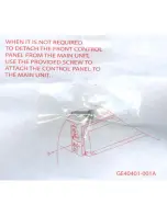
Page 23: ...WHEN IT IS NOT REQUIRED TO DETACH THE FRONT CONTROL PANEL FROM THE MAIN UNIT USE THE PROVIDED SCREW TO ATTACH THE CONTROL PANEL TO THE MAIN UNIT eJ GE40401 001A ...

Page 24: ......

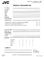
Page 25: ...ewsletter 2 Would you like to receive special offers from JVC 3 Have you purchased an extended warranty for this product Date of Purchase Model Number Serial Number Purchase Price Dealer Yes No Yes No Yes No On a scale of 1 to 5 with 5 being the best please rate each of the following attributes about your new JVC product 8T 51 044 1 0208 Instructions Fold at crease and tape open edge in the middle...

Page 26: ...PLACE STAMP HERE PRODUCT REGISTRATION CARD I QUESTIONNAIRE USA CUSTOMERS ONLY Registering your product will allow us to contact you in the unlikely event a product safety notification is required This form is for Product Registration purposes only Failure to return this form does not diminish your rights during the warranty period THANK YOU FOR PURCHASING THIS JVC PRODUCT REGISTER ONLINE AT REGIST...

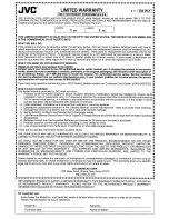
Page 27: ...urchase of the JVC product requiring service c The JVC product must be brought in for service to an authorized JVC Service Centre 2 Limitation This Warranty shall not apply to a Repair or replacement of any cabinets batteries plates connection cords anten nas dust covers knobs speaker grills speaker cones projection screens projection screen savers and all accessories b Any defects caused or repai...

Page 28: ...ers Remote Controls Headphones Microphones and 90 DAYS 90 DAYS Projector Lamps Adaptateurs AC Teli commande Casque D ecoute Microphones 90 JOURS 90 JOURS et Lampe de Projecteur Wood Cone Speakers 5 5 Enceinte 11 Cone en Bois All Other Categories 1 1 Toutes les autres categories I Any defects caused by fire flood lightning power surge or other events beyond the control of JVC m FOR AUTO PRODUCTS Wa...

Page 29: ...ICE CENTER LIKE TO PURCHASE ACCESSORIES JVC IS HERETO HELP TOLL FREE 1 800 252 5722 http www jvc com Remember to retain your Bill of Sale for Warranty Service Do not attempt to service the product yourself Caution To prevent electrical shock do not open the cabinet There are no user serviceable parts inside Please refer to qualified service personnel for repairs BT 51 018 6 1008 Printed in Indones...

Page 30: ...one other than a service facility authorized by JVC to render such service or if affixed to any attachment not provided with the products or if the model or serial number has been altered tampered with defaced or removed 2 Initial installation installation and removal from cabinets or mounting systems 3 Operational adjustments covered in the Owner s Manual normal maintenance video and audio head c...

Reviews: