


REV
. 10
22-04-2020
INSTALLATION
,
USE AND MAINTENANCE MANUAL
–
PN
19 / 40
Jurop
SpA
Via Crosera n° 50
33082 Azzano Decimo, PN (Italia)
T
EL
. +39 0434 636811 F
AX
. +39 0434 636812
http://www.jurop.it
e-mail: [email protected]
Pos
Code
Description
1
-
VANE
2
1610006600
FLANGE
3
1610500400
FRONT OIL SEAL FLANGE
4
1610500500
FLANGE
5
1680700400
FLANGE GASKET
6
4022200110
SEAL 72X48X15
7
4022200240
O-RING 4825
8
4023100040
BEARING 6308
9
4026300020
COMPENSATION RING
10
4026305614
SELF-BLOCKING NUT M24X2
Disassemble operation
• After removing the cardan guard and the front shaft (smooth /
broached), loosen and remove the self-locking flanged nut (10) and the
direct intake transmission flange (2).
• Remove the front oil seal flange (3) and its gasket (5).
• Remove the decompressor flange (4) using the threaded holes for
removal. Do not lose the underlying O-Ring (7).
• Support the shaft before removing the flange: the weight of the
rotor must not cause any abnormal stress on the internal components.
• Remove the worn vanes (1).
• Complete the disassembly procedure:
Remove the bearing (8) and the seal rings (6) from the
decompressor flange (4);
Do not lose the compensation ring (9).
Remove the seal ring (6) from the front flange (3).
Assemble operation
• Fit the seal ring (6) on the transmission flange (4).
• Reassemble the components in the following order:
Replace the O-Ring (7) and secure using grease in the front
flange seat.
Replace the seal ring (6).
Fit the flange (4) on the body: avoid damaging the seal rings
(6) while fitting them on the shaft. Insert the bearing (8)
properly and all the way into its seat and fit the compensation
ring (9).
Replace the seal ring (6) on the flange (3) and mount on the
flange (4) replacing the gasket (5).
Direct intake transmission flange (2) and self-locking flanged
nut (10)
Smooth / broached shaft
Cardan shaft guard.
PN with Gearbox
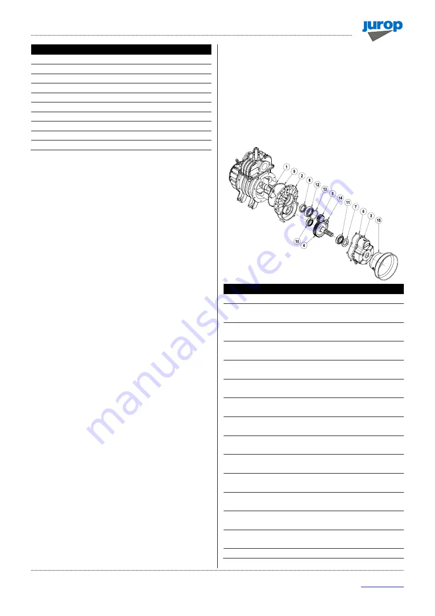
Disassemble operation
• Remove the transmission, if any. Check its conditions.
• Remove the cardan shaft guard (15).
• Remove the gearbox (3) and relative gasket (6).
• Remove the seal ring (7) and the bearing (11) fitted on the gear
wheel (4). At the same time loosen and remove the flange nut (14).
• Remove the gear wheel (4) and pinion (5).
• Remove the decompressor flange (2) using the threaded holes for
removal. Do not lose the underlying O-Ring (9).
• Support the shaft before removing the flange: the weight of the
rotor must not cause any abnormal stress on the internal components.
• Remove the worn vanes (1).
• Complete the disassembly procedure:
Remove the bearings (10) and (12), the seal ring (8) from the
decompressor flange (2);
Do not lose the compensation ring (13) fitted in models PN 45-
58-84-106.
Pic. 6.8
Pos
Code
Description
1
-
VANE
2
1610503900
GEARBOX FLANGE PN23-33
1610500000
GEARBOX FLANGE PN45-…-106
3
1612501300
GEARBOX PN23-33
1612503100
GEARBOX PN45-…-106
4
1651000300
GEAR PN23-33
1651000000
GEAR PN45-…-106
5
1651000200
PINION PN23-33
1651000100
PINION PN45-…-106
6
1680700900
GASKET PN23-33
1680700000
GASKET PN45-…-106
7
4022200032
SEAL PN23-33
4022200040
SEAL PN45-…-106
8
4022200025
SEAL PN23-33
4022200110
SEAL PN45-…-106
9
4022200230
O-RING PN23-33
4022200240
O-RING PN45-…-106
10
4023100018
BEARING PN23-33
4023100020
BEARING PN45-…-106
11
4023100020
BEARING PN23-33
4023100130
BEARING PN45-…-106
12
4023100018
BEARING PN23-33
4023100040
BEARING PN45-…-106
13
4026510025
SEEGER PN23-33
4026300020
SEEGER PN45-…-106
14
4026305612
NUT M20X1,5
4026305614
NUT M24X2
15
4029602806
DRIVE SHAFT PROTECTION