jurop PN 106 Installation, Use And Maintenance Manual Download Page 16

REV

. 10

22-04-2020

INSTALLATION

,

USE AND MAINTENANCE MANUAL

PN

16 / 40

Jurop

SpA

Via Crosera n° 50
33082 Azzano Decimo, PN (Italia)

T

EL

. +39 0434 636811 F

AX

. +39 0434 636812

http://www.jurop.it

e-mail: [email protected]

preventing oxidation. When the detergent mix is finished, continue
running the pump at the lo west possible vacuum rate for a few
minutes, then close venting and suction valves up to 50-60%
maximum, for a couple of minutes. With this operation the pump will
dry from the heated air and protected from the chemical attack of
the detergent.

7.

Washing the pump with this detergent guarantees a protection after
some days of inoperativity. If the pump is not used for more than
two weeks, after having washed and dried the inner parts as
described above, it is recommended to suck slowly 200 cc anti-rust
and water-repellent protective oil (or, if not available, a very fluid
gear oil).

Attention: do not carry out also this operation on
very hot pumps (for example after a working day)

until they have cooled down.

In case the exhaust line cannot be disconnected,
drain the liquids accumulated in the separator of
the exhaust silencer.

• Do not convey the exceeding flow outlet towards the suction port.
• Control the air flow by adjusting the rotation speed: do not use the

safety relief valve to discharge the exceeding flow.

• Do not squeeze the hoses/pipes.
• If the decompressor operates in vacuum or under pressure with a

capacity environment (such as a cistern) and is configured in the “FL”
flanged version (without manifold with 4-way valve and non-return vale),
it is advisable to intercept the working line of the machine when it is
stopped, to prevent contrary rotations until the rebalancing of the
pressures. The interception can take place through a controlled valve or
an automatic unidirectional valve (swing valve).

• Avoid starting the pump under load: motor and drive system can be

excessively stressed.

6.1.

Ordinary maintenance

• Any interventions must be performed when the machine is cold, stopped and switched off.
• Installation and maintenance must be operated only by qualified personnel wearing the proper clothes and the necessary tools as well as

protection devices.

• Use suitable protection equipment (gloves, protection glasses, boots...)
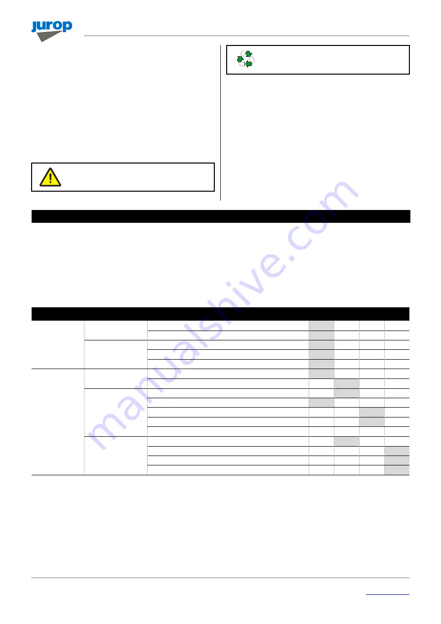
• In the following table summarizes the main controls to be performed and the frequency of intervention.

Operating
Condition

Maintenance Area

Check

8

H

50

H

500

H

1000H

OPERATING

Vacuum line

Check safety valve (non-return valve)
Operating pressure

Transmission / Pump

Lubrication: dripping into oilers
Rotation speed
Sound pressure level (also HDR motor)

STANDSTILL

Vacuum line

Suctions filters
4-way changeover valve: check and lubricate

Pump

Clean oilers glasses
Check oil level
Check vanes wear
Change oil (*)
Pump’s inner washing (**)

Overall

Greasing
Check cardan shaft drive
Chack transmission pulley
Swing valve wear check

(*) The first oil change must be done inside 500 hours operation. Following changes every 5000 hours or 12 months. In order to choose the most

suitable oil, see paragraph 2.5.

(**) After operation in dusty environments, after accidental sucking of liquids inside the pump or before a long inoperativity period it is

recommended to wash the pump inside according to the procedure described at paragraph 5.2.

6. Maintenance

Summary of Contents for PN 106

Page 1: ...I IN NS ST TA AL LL LA AT TI IO ON N U US SE E A AN ND D M MA AI IN NT TE EN NA AN NC CE E M MA AN NU UA AL L EN PN Rev 10 22 04 2020 O OR RI IG GI IN NA AL L I IN NS ST TR RU UC CT TI IO ON NS S...

Page 2: ...1 FAX 39 0434 636812 http www jurop it e mail info jurop it 2020 Jurop Azzano Decimo PN Reproduction electronic storage and dissemination even partial are prohibited Jurop reserves the right to modify...

Page 3: ...10 4 3 Storing in the warehouse 10 4 4 Handling and installation 10 4 5 Mounting 10 4 6 Vacuum Pressure Line 11 4 7 Vacuum pressure inverter Remote control actuators 12 4 8 Pump mounting Drive connect...

Page 4: ...r oilers damaged remarkably If these safety rules are not respected the pump or system can be damaged Suggestions for an environment friendly use of the pump Useful information for an easy usage and m...

Page 5: ...ter fins of the body made of high strength cast iron The check valve is integrated in the decompressor The decompressors feature a 4 way manifold On request a 5 way Mixer type diverter valve is provid...

Page 6: ...275 70 16 70 190 180 60 76 80 157 504 5 240 270 275 PN 106 694 319 5 70 16 70 290 174 5 60 76 80 169 517 240 285 339 PN 106 SL 685 5 319 5 70 16 70 290 174 5 60 76 80 169 517 240 285 339 PN Gearbox t...

Page 7: ...N M rpm 540 540 540 1000 540 1000 540 1000 540 1000 Air flow at free air condition l min 2600 3600 5300 6500 9000 11000 m h 156 216 318 390 540 660 Air flow at 60 vacuum rate l min 2100 2900 4500 5800...

Page 8: ...T2 temperature during delivery 2 4 Sound pressure level Lw A Noise power of the only pump without drive trasmission suction group mufflers dB A RPM VACUUM PRESSURE PN 23 PN 33 PN 45 PN 58 PN 84 PN 10...

Page 9: ...of the pump the insertion in the housing machine and the typology of the same the designer of the housing machine must apply safety signals pictograms to warn the operator on the risk still present T...

Page 10: ...r the machine when moving more than 50 cm from the ground Proceed with the final lifting only near the installation point Harness the machine with suitable straps chains near the main body paying atte...

Page 11: ...rator reach A non return valve on suction pipe avoids rotation in the opposite direction when the pump stops To avoid that foreign liquids will enter the vacuum pump it is necessary to mount on the su...

Page 12: ...of PN Besides reducing the noise produced by the air flow along the vacuum line the silencer also traps the oil vapor at the outlet due to decompressor lubrication 4 7 Vacuum pressure inverter remote...

Page 13: ...ction as indicated on the pump front conveyor protection Follow the instructions of the cardan shaft s manufacture Use the cardan guard supplied with the pump by fixing it to the pump itself Use the c...

Page 14: ...dicated by the arrow on the pump front flange Draining connect directly to the tank above the maximum oil level Operating without draining line may damage the motor Pic 4 6 Distributor open centre dis...

Page 15: ...may cause quick wear and possible breakdown of vanes Do not start running the pump under load that causes stress to the drive system and the hydraulic motor Check rotation speed The vacuum pump must...

Page 16: ...and non return vale it is advisable to intercept the working line of the machine when it is stopped to prevent contrary rotations until the rebalancing of the pressures The interception can take plac...

Page 17: ...rt near the outlet inlet a 6 mm diameter dipstick with the chamfered end facing towards the bottom After resting the dipstick on the rotor carry out a first measurement by making a mark on the dipstic...

Page 18: ...scription 1 VANE 2 1610500900 FLANGE 3 1610504000 FRONT FLANGE 4 1680701000 FLANGE GASKET 5 4022200025 SEAL 55X35X10 6 4022200037 SEAL 65X48X10 7 4022200230 O RING 4575 8 4023100018 BEARING 6206 NMQ 9...

Page 19: ...Replace the seal ring 6 on the flange 3 and mount on the flange 4 replacing the gasket 5 Direct intake transmission flange 2 and self locking flanged nut 10 Smooth broached shaft Cardan shaft guard PN...

Page 20: ...ng use a torque wrench set at 160 Nm for M20X15 nut PN23 33 and 350Nm for M24X2 nut PN45 106 Carry out a continuous movement of about 30 without interruptions until the nut stops when the wrench click...

Page 21: ...brication pump Damaged drive system Change the damaged parts Frozen up pump Warm up the pump Cause Solution 4 way valve handle in neutral position Move the handle against the resting pin Worn vanes Ch...

Page 22: ...Iron Steel Alluminum Copper Bronze Rubber Vane Oil Plastic PN 23 83 14 0 4 0 4 0 2 0 2 0 6 0 7 0 8 PN 33 84 13 0 3 0 3 0 2 0 2 0 7 0 6 0 7 PN 45 85 12 0 6 0 4 0 1 0 2 0 5 0 5 0 5 PN 58 86 12 0 6 0 3 0...

Page 23: ...osera n 50 33082 Azzano Decimo PN Italia TEL 39 0434 636811 FAX 39 0434 636812 http www jurop it e mail info jurop it PN 23 33 DIRECT TRANSMISSION PICTURE SHOWS PN 23 PD SMO SHAFT COD A010303110 PN 23...

Page 24: ...600 MANIFOLD 1 16 1640100000 OIL TANK COVER 1 HYDRAULIC TRANSMISSION 17 1642600000 PIPLINE PROTECTION 2 H1 1470101600 COUPLING 1 18 1650000500 FRONT SMOOTH SHAFT 1 H2 1612504900 HYDRAULIC BRACKET 1 16...

Page 25: ...PN 23 33 25 40 Jurop SpA Via Crosera n 50 33082 Azzano Decimo PN Italia TEL 39 0434 636811 FAX 39 0434 636812 http www jurop it e mail info jurop it PN 23 33 WITH GEARBOX PICTURE SHOWS PN 23 M COD A01...

Page 26: ...FT PROTECTION 1 1621502700 ROTOR PN33 LEFT 1 11 1622002600 SHAFT 1 DX 4026414614 PIN 3X30 only for right model 1 12 1623500500 MANIFOLD CAP 1 13 162409YKB0 SPACER 1 1892000100 GASKET KIT PN 23 33 M 1...

Page 27: ...imo PN Italia TEL 39 0434 636811 FAX 39 0434 636812 http www jurop it e mail info jurop it PN 45 58 84 DIRECT TRANSMISSION PICTURE SHOWS PN 45 PD SMO SHAFT COD A030809110 PN 45 PD COD A03 PN 58 PD COD...

Page 28: ...C MOTOR PN 45 1 21 1663005100 DELIVERY PIPE PN 45 D RIGHT M LEFT 1 4024107008 HYDRAULIC MOTOR PN 58 1 1663005500 DELIVERY PIPE PN 45 D LEFT M RIGHT 1 4024107005 HYDRAULIC MOTOR PN 84 1 1663005200 DELI...

Page 29: ...29 40 Jurop SpA Via Crosera n 50 33082 Azzano Decimo PN Italia TEL 39 0434 636811 FAX 39 0434 636812 http www jurop it e mail info jurop it PN 45 58 84 WITH GEARBOX PICTURE SHOWS PN 45 M COD A0332091...

Page 30: ...IVE SHAFT PROTECTION 1 13 162409YKB0 SPACER 1 14 1624202300 SPACER 1 DX 4026414614 PIN 3X30 only right model 1 15 1627500000 MANIFOLD 1 16 1640101100 OIL TANK COVER 1 1892000000 GASKET KIT PN 45 58 84...

Page 31: ...Via Crosera n 50 33082 Azzano Decimo PN Italia TEL 39 0434 636811 FAX 39 0434 636812 http www jurop it e mail info jurop it PN 106 DIRECT TRANSMISSION PICTURE SHOWS PN 106 PD SMO SHAFT COD A060909510...

Page 32: ...SION FLANGE 1 23 1663018500 LUBRICATION PIPE D LEFT M RIGHT 1 H3 1612501400 HYDRAULIC BRACKET 1 1663018600 LUBRICATION PIPE D RIGHT M LEFT 1 H4 4024107001 HYDRAULIC MOTOR 1 24 1663018600 LUBRICATION P...

Page 33: ...TA SHEET PN 106 33 40 Jurop SpA Via Crosera n 50 33082 Azzano Decimo PN Italia TEL 39 0434 636811 FAX 39 0434 636812 http www jurop it e mail info jurop it PN 106 WITH GEARBOX PICTURE SHOWS PN 106 M C...

Page 34: ...ON 1 17 1640101100 OIL TANK COVER 1 18 1642600000 PIPELINE PROTECTION 2 DX 4026414614 PIN 3X30 only for right model 1 19 1651000000 GEAR 1 20 1651000100 PINION 1 1892000000 GASKET KIT PN 106 M 1 21 16...

Page 35: ...20 35 40 Jurop SpA Via Crosera n 50 33082 Azzano Decimo PN Italia TEL 39 0434 636811 FAX 39 0434 636812 http www jurop it e mail info jurop it PN 106 WITH SIDE OIL TANK AND GEARBOX 1000 RPM PICTURE SH...

Page 36: ...0 GEAR 1 78 4026401806 PIN 10X36 2 20 1651009700 GEAR 1 79 4026500018 TAB 6X10 1 21 1663018500 LUBRICATION PIPLINE 1 80 4026702000 FITTING 4X1 8 6 22 1663062900 LUBRICATION PIPLINE 1 81 4026706000 FIT...

Page 37: ...7 168529TFB0 SPACER 1 H7 16732001E0 COUPLER 1 P8 1691000200 SPRING 1 H8 1680700200 CONVEYOR CAP GASKET 1 P9 4022100100 GREASER M6X1 1 H9 168409PQB0 RING NUT 1 P10 4022200005 SEAL 37X27X7 1 H10 168529T...

Page 38: ...INC 2 O5 4026308007 NUT M12 ZINC 2 F5 4026350709 WASHER GROWER 12 ZINC 2 O6 4026350709 WASHER GROWER 12 ZINC 2 1852104700 SUCTION CONVEYOR KIT 80 18521024E0 DELIVERY CONVEYOR KIT 80 F1 1627100300 CONV...

Page 39: ...EYOR 76 MIX 1 1627100900 SUCTION CONVEYOR 80 MIX 1 M8 1627500100 MANIFOLD 1 M8 1627500100 MANIFOLD 1 M9 1680600100 MANIFOLD GASKET 1 M9 1680600100 MANIFOLD GASKET 1 M10 1680700200 GASKET 1 M10 1680700...

Page 40: ...fo jurop it Model Issue date Revision No Revision date Filled out by Viewed by PN 01 01 2002 10 22 04 2020 U T A T Jurop SpA Via Crosera 50 33082 Azzano Decimo PN ITALY Tel 39 0434 636811 Fax 39 0434...

Reviews: