


5. Install the replacement fan.
6. Tighten the captive screws on the faceplate of the fan module by using your fingers. If you are unable
to tighten the captive screws by using your fingers, use the screwdriver.
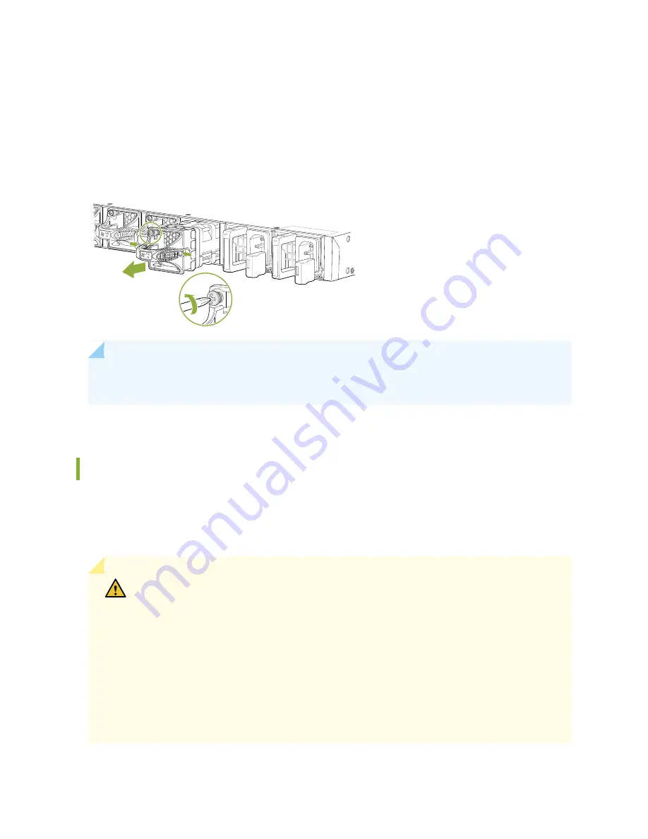
Figure 59: Removing a Fan Module from a QFX5120 Switch
g022522
NOTE:
Both the fan modules must be installed and operational for optimal functioning of the
switch.
Installing a Fan Module in a QFX5120 Switch
QFX5120-48Y comes with 4+1 redundant fans and QFX5120-32C comes with 5+1 redundant fans. Each
fan module is a hot-removable and hot-insertable field-replaceable unit (FRU) installed in the rear panel
of the switch. You can remove and replace it without powering off the switch or disrupting switch functions.
CAUTION:
Do not mix:
•
Fan modules with different airflow labels (AIR IN (AFI) and AIR OUT (AFO)) in the same
chassis.
•
Power supplies with different airflow labels (AIR IN (AFI) and AIR OUT (AFO)) in the
same chassis.
•
Power supplies and fan modules with different airflow labels (AIR IN (AFI) and AIR
OUT (AFO)) in the same chassis.
•
AC and DC power supplies in the same chassis.
122
Summary of Contents for QFX5120 Series
Page 1: ...QFX5120 Switch Hardware Guide Published 2019 10 15 ...
Page 18: ......
Page 62: ......
Page 87: ......
Page 116: ......
Page 138: ...5 CHAPTER Troubleshooting Hardware Troubleshooting QFX5120 Components 145 ...
Page 139: ......
Page 145: ......
Page 163: ...Restricted Access Warning 169 ...
Page 178: ...Jewelry Removal Warning 184 ...
Page 181: ...Operating Temperature Warning 187 ...
Page 190: ...DC Power Disconnection Warning 196 ...
Page 194: ...DC Power Wiring Sequence Warning 200 ...


