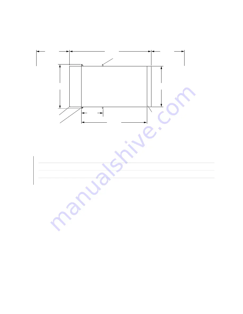
Figure 63: Chassis Dimensions and Clearance Requirements for a DC-powered MX2010 with an Extended
Cable Manager
g008201
38.14 in.
(96.9 cm)
19.0 in.
(48.3 cm)
17.5 in.
(44.45 cm)
Front
Rear
33.5 in.
(85.1 cm)
36.0 in.
(91.44 cm)
Clearance
required
Top view
Extended cable
manager
Front mounting
flange
36.0 in.
(91.44 cm)
Clearance
recommended
Center mounting
flange
12.0 in.
(30.5 cm)
Extended DC
power cable
manager
RELATED DOCUMENTATION
MX2010 Rack Requirements | 135
MX2010 Rack-Mounting Hardware | 43
MX2010 Cabinet Size and Clearance Requirements | 128
MX2010 Cabinet Airflow Requirements | 127
150
Summary of Contents for MX2010
Page 1: ...MX2010 Universal Routing Platform Hardware Guide Published 2019 12 03...
Page 28: ......
Page 30: ...MX2010 Power System Description 95 MX2010 Cooling System Description 45 4...
Page 144: ...MX2010 DC Power 48 V System Electrical Specifications 201 122...
Page 146: ......
Page 233: ......
Page 273: ...Figure 98 Loading the MX2010 Router into the Rack g007436 256...
Page 294: ...Figure 113 Reinstalling an AC Power Distribution Module g007440 D 277...
Page 295: ...Figure 114 Reinstalling a DC Power Distribution Module 48 V D g007432 278...
Page 373: ...4 PART Installing and Replacing Components Installing Components 359 Replacing Components 429...
Page 374: ......
Page 620: ......
Page 715: ...6 PART Troubleshooting Hardware Troubleshooting Components 703...
Page 716: ......
Page 744: ......
Page 772: ......
Page 775: ...763...
Page 783: ...772...
Page 796: ...Jewelry Removal Warning 787...
Page 799: ...Operating Temperature Warning 790...
Page 808: ...DC Power Disconnection Warning 799...
Page 812: ...DC Power Wiring Sequence Warning 803...


