Copyright © 2011, Juniper Networks, Inc.
17
APPLICATION NOTE - Configuring and deploying the AX411 Wireless Access Point
Creating a Guest Network using Firewall Authentication
In our final example, we will use firewall authentication to authenticate users trying to access a guest network. New
users will be redirected to a local portal running in the srX series where they will be authenticated. The user database
can be local or, as in the previous examples, rAdIus authentication can be used. firewall authentication will only be
used in the guestNet; WifiNet will do rAdIus-based MAC authentication instead.
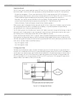
Figure 8: Firewall authentication
In this example, both radios broadcast both ssIds (WifiNet and guestNet) simultaneously, so clients can associate
using either of the following protocols to any ssId 802.11a/b/g or n.
INTERNET
OFFICE
ge-0/0/7.0 (trust)
192.198.254.1/24
Radius Server
192.168.254.2
Client
AP-1
00:de:ad:10:75:00
AP-2
00:de:ad:10:76:00
AP-3
00:de:ad:10:77:00
CorpNet and GuestNet SSIDs
Clients associated to CorpNet are tagged with VLAN tag 2
Clients associated to GuestNET are tagged with VLAN tag 3
Firewall Auth
The GuestNet zone will do Firewall Authentication
and redirect the first HTTP requests to a local portal
SRX
Series
ge-0/0/0.0
(untrust)
198.0.0.1/24
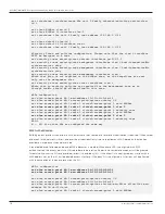
#Enable the http connections to the vlan.3 interface, where the captive portal
will be used
set system services web-management http interface vlan.3
set system services dhcp name-server 4.2.2.2
set system services dhcp pool 192.168.2.0/24 address-range low 192.168.2.2
set system services dhcp pool 192.168.2.0/24 address-range high 192.168.2.254
set system services dhcp pool 192.168.2.0/24 router 192.168.2.1
set system services dhcp pool 192.168.2.0/24 address-range low 192.168.2.2
set system services dhcp pool 192.168.2.0/24 address-range high 192.168.2.254
set system services dhcp pool 192.168.2.0/24 router 192.168.2.1
#The 192.168.3.2 address is used by the local portal, so it must be excluded from
the DHCP pool
set system services dhcp pool 192.168.3.0/24 address-range low 192.168.3.3
set system services dhcp pool 192.168.3.0/24 address-range high 192.168.3.254
set system services dhcp pool 192.168.3.0/24 router 192.168.3.1
#Interfaces and VLANs configuration is almost identical to the one shown in
previous examples
set interfaces interface-range APs member ge-0/0/1
set interfaces interface-range APs member-range fe-0/0/2 to fe-0/0/3
set interfaces interface-range APs unit 0 family ethernet-switching port-mode
trunk
set interfaces interface-range APs unit 0 family ethernet-switching vlan members
default
set interfaces interface-range APs unit 0 family ethernet-switching vlan members


