background image

Room controller display compact module

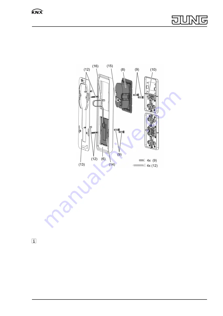
Connect controller module (8) to the KNX using KNX device connection terminal (11) and
push onto the supporting frame.

Fasten controller module (8) and push-button extension module (12) to supporting frame
using the enclosed plastic screws (8). Tighten the plastic screws only lightly.

Before mounting the control surfaces (10), load the physical address into the device (see
chapter 5.2. commissioning).

Figure 3: Mounting with push-button extension module

(13)

Supporting frame for mounting with push-button extension module

(14)

Push-button extension module

(15)

Slot for push-button extension module

(16)

Push-button extension module connecting cable

5.2 Commissioning

Loading the physical address and application software

Project design and commissioning with ETS3.0d with Patch A or more recent.

The device is connected and ready for operation.

The buttons are not mounted yet.

If the device does not receive any application software, or the wrong application software,
then the blue operation LED flashes slowly.

5 / 7

32573243

16.04.2020

J:0082573243

Summary of Contents for KNX 4093 KRM TS D

Page 1: ...CD with button 2 Buttons 1 and 2 3 Operating and status LED 3 Function System information This device is a product of the KNX system and complies with the KNX directives Detailed tech nical knowledge...

Page 2: ...eft lower right entire surface Operation depends on the specific function Switch Short press on button Dim Long press on the button The dimming process ends when the button is released Move Venetian b...

Page 3: ...ode heating Raising for night mode cooling Changing the operating mode Fan controller Displaying the time Displaying the current room temperature Displaying the current temperature setpoint Displaying...

Page 4: ...g frame 13 When mounting on only one appliance box countersink the lower screws into the wall e g with a 6 x10 mm hole Use supporting frame as template DANGER When mounting with 230 V devices under a...

Page 5: ...3 Mounting with push button extension module 13 Supporting frame for mounting with push button extension module 14 Push button extension module 15 Slot for push button extension module 16 Push button...

Page 6: ...e mounting spider is not required to mount the buttons The physical address is loaded into the device Place the buttons 10 on the device in the correct orientation and snap in with a short push Note t...

Page 7: ...SA Cover kit 3 gang Art no 503 TSA Cover kit 4 gang Art no 504 TSA 6 3 Warranty The warranty is provided in accordance with statutory requirements via the specialist trade ALBRECHT JUNG GMBH CO KG Vol...

Reviews: