background image

© JUNG Hebe- und Transporttechnik GmbH

JKB revolving transport trolleys / JLF multi-purpose trolleys

- 46 -

English

4.4 Commissioning 

DANGER

The total weight of the transport load and the position 

of the centre of gravity must be known before the 

lifting and moving operation. The weight of the 

transport load must not be greater than the permitted 

carrying capacity of the trolleys. Otherwise, tipping or 

slipping can lead to injuries or even to fatal accidents. 

Always determine the centre of gravity before using 

JUNG trolleys.
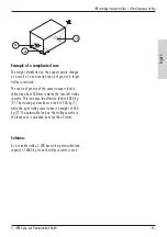
For the determination of the centre of gravity, see 

"Centre of gravity determination and positioning of 

transport trolley and jack", page 39.

WARNING

Always place the trolleys on a flat, firm, non-slip sur-

face. Observe the point load and make sure the ground 

is sufficiently stable.

WARNING

When using the trolley with a transport load, there 

is a danger of crushing. Always wear safety clothing. 

Otherwise, accidents and injuries could occur.

WARNING

If the height of the load exceeds the length of the 

side to be lifted, appropriate safety precautions must 

be taken in order to prevent the load from toppling 

over. This applies in particular to machines in which 

the centre of gravity is located in the upper half of 

the load. Inform yourself about the dimensions of the 

transport load and determine the centre of gravity in 

order to avoid injuries.

DANGER

Operating personnel has to ensure that other unin-

volved persons keep a safety distance of at least 1.5 

times the height of the transport load on all sides of 

the transport load. If there is a risk that uninvolved 

persons could suddenly enter the danger area, the 

danger area must be closed off appropriately. Failure to 

do so can result in injury or even fatal accidents.

NOTE

For safe lifting, the use of hydraulic JUNG jacks is 

recommended.

NOTE

Observe the operating instructions of the JUNG jacks.

DANGER

Be sure to use the connecting rod for the individual 

trolleys. As a result, the trolleys are guided parallel to 

the load if the floor is even, clean and without steps. 

Otherwise, tipping or slipping can lead to injuries or 

even to fatal accidents. Secure the transport load.

CAUTION

Be sure to observe the order of the work steps.

Summary of Contents for JKB 3

Page 1: ...piques et ch ssis assist s Carrelli giroscopici e servocarrelli Draaibare onderstellen en servo onderstellen Betriebsanleitung Operating instructions Instrucciones de servicio Mode d emploi Istruzioni...

Page 2: ...Notizen Notes Notas Notes Note Aantekeningen...

Page 3: ...forderungen an den Aufstellplatz 15 4 1 1 Schwerpunktermittlung und Positionierung von Transportfahrwerk und Heber 15 4 2 Optionales Zubeh r 19 4 3 Auswahl des geeigneten Fahrwerks 20 4 4 Inbetriebnah...

Page 4: ...dteil des Produkts und muss deshalb aufbe wahrt sowie bei Weitergabe des Produkts mitgegeben werden 1 2 Nicht bestimmunsgem e Verwendung Die Fahrwerke sind nicht f r die Bef rderung auf ffentlichen St...

Page 5: ...ckgreifen m ssen regelm ig mindestens einmal j hrlich durch eine bef higte Person unterwiesen werden Das blo e Aush ndigen oder Aush ngen von Vorschriften Betriebsanleitungen oder Warntafeln gen gt da...

Page 6: ...KB 3 H he mm 110 Gewicht kg 37 Traglast kg 10 000 JKB 4 H he mm 110 Gewicht kg 43 Traglast kg 4 000 JKB 6 H he mm 110 Gewicht kg 44 Traglast kg 6 000 JKB 7 5 H he mm 110 Gewicht kg 63 5 Traglast kg 7...

Page 7: ...Transporttechnik GmbH Kreiselfahrwerke JKB Servofahrwerke JLF 7 Deutsch 3 bersicht 3 1 Kreiselfahrwerke JKB JKB 1 5 Positionsnummer Benennung 1 Aufnahmeteller 2 Arretierungsschraube 3 Bolzen 2 3 1 M P...

Page 8: ...und Transporttechnik GmbH Kreiselfahrwerke JKB Servofahrwerke JLF 8 Deutsch JKB 3 Positionsnummer Benennung 1 Aufnahmeteller 2 Arretierungsschraube 3 Bolzen 4 Aussparung f r Verzurrgurte 5 Handgriff...

Page 9: ...orttechnik GmbH Kreiselfahrwerke JKB Servofahrwerke JLF 9 Deutsch JKB 4 Positionsnummer Benennung 1 Handgriff 2 Aussparung f r Verzurrgurte 3 Aufnahmeteller 4 Arretierungsschraube 5 Bolzen 1 2 3 4 5 M...

Page 10: ...JUNG Hebe und Transporttechnik GmbH Kreiselfahrwerke JKB Servofahrwerke JLF 10 Deutsch JKB 7 5 Positionsnummer Benennung 1 Aufnahmeteller 2 Arretierungsschraube 3 Bolzen 3 1 2 M P 44A 0059 1 2 3...

Page 11: ...JUNG Hebe und Transporttechnik GmbH Kreiselfahrwerke JKB Servofahrwerke JLF 11 Deutsch JKB 7 5 Positionsnummer Benennung 4 Aussparung f r Verzurrgurte 5 Handgriff 4 4 5 4 4 M P 44A 0060 4 4 4 4 5...

Page 12: ...JUNG Hebe und Transporttechnik GmbH Kreiselfahrwerke JKB Servofahrwerke JLF 12 Deutsch JKB 10 Positionsnummer Benennung 1 Aufnahmeteller 2 Bolzen 3 Handgriff 1 2 3...

Page 13: ...JUNG Hebe und Transporttechnik GmbH Kreiselfahrwerke JKB Servofahrwerke JLF 13 Deutsch JLF 3 5 Positionsnummer Benennung 1 Arretierungsschraube 2 Bolzen 2 1 M P 44A 0057 3 2 Servofahrwerke JLF 1 2...

Page 14: ...JUNG Hebe und Transporttechnik GmbH Kreiselfahrwerke JKB Servofahrwerke JLF 14 Deutsch JLF 3 5 Positionsnummer Benennung 3 Aufnahmeteller 3 M P 44A 0058 3...

Page 15: ...chen Unf llen f hren Bestimmen Sie immer den Schwerpunkt bevor Sie JUNG Kreisel oder Servofahr werke verwenden 4 1 1 Schwerpunktermittlung und Positionie rung von Transportfahrwerk und Heber GEFAHR Be...

Page 16: ...ben dass das Hebegut ber die gegen berliegende Drehkante waagerecht angehoben wird Das Hebegut maximal 1 mm mit dem Hebeger t anheben An allen vier Seiten in gleicher Weise den Druck ermitteln und not...

Page 17: ...eweils den h heren der beiden Druckwerte der parallelen Seiten als Referenzwert verwenden Beispiel Seite 1 und 2 300 bar 1000 mm 230 bar 767 mm Beispiel Seite 3 und 4 300 bar 1500 mm 200 bar 1000 mm D...

Page 18: ...bt sich dass die gegen berliegende Seite die Drehachse ist Die anderen beiden gegen berliegen den Seiten sind innerhalb des Dreiecks als Hebepunkte verboten da hier das Hebegut kippen w rde Die folgen...

Page 19: ...falschem Ansetzen z B auf oder in der N he der angepeilten Linie besteht Kippgefahr da sich die Dreh kante verlagern kann Das Transportgut kippt unkontrol liert Es besteht Verletzungsgefahr 4 2 Option...

Page 20: ...Das gesamte Gewicht der zu hebenden und bewegenden Last und die Lage des Schwerpunkts m ssen vor dem Hebe und Bewegungsvorgang bekannt sein F r die Auswahl des geeigneten Fahrwerks muss der Schwerpunk...

Page 21: ...nsportguts ist um etwa 500 mm in Richtung der hinteren linken Fahrwerkskas sette verschoben Dadurch erh ht sich die wirkende Last auf 4800 kg 3 Das Lenkwerk tr gt eine Last von 900 kg 1 und die rechte...

Page 22: ...gegen das Kippen der Last vorzunehmen Dies gilt be sonders bei Maschinen bei denen sich der Schwerpunkt in der oberen H lfte der Last befindet Informieren Sie sich ber die Ma e des Transportguts und f...

Page 23: ...heben und mit Unterlagen bis auf 5 mm ber der angegebenen H he stabil unterbauen Gro e Neigung vermeiden da Kippgefahr durch Schwer punktverlagerung besteht insbesondere bei labilem Transportgut Zwei...

Page 24: ...ls Zugfahrzeug an den gew nschten Standort bewegen GEFAHR Das Hebegut niemals einseitig bis auf die zu unterfahrende H he anheben da hier enorme Kipp und Rutschgefahr besteht WARNUNG Transportgut lang...

Page 25: ...te wirken F r das Einfetten handels bliches Hochleistungs Lagerfett verwenden Verwenden Sie f r das Einfetten aller Lager einen Pinsel Fetten Sie mindestens einmal j hrlich die Lager der Fahrwerke 5 2...

Page 26: ...Richtlinien des EG Rates 2006 42 EG Hiermit erkl ren wir dass die Bauart der Lenk und Transportfahrwerke wie oben benannt Fabrikat JUNG zur Verbindung mit anderen Maschinen zu einer Maschine bestimmt...

Page 27: ...B revolving transport trolleys 31 3 2 JLF multi purpose trolleys 37 4 Operation 39 4 1 Requirements for the placement area 39 4 1 1 Determining the centre of gravity and positioning the transport trol...

Page 28: ...e read and observed The operating manual is part of the product and must therefore be kept and transferred along with the product if it is handed on 1 2 Improper use The trolley are not intended for t...

Page 29: ...in charge of transporting loads and who use these devices for this purpose must be regularly instructed by a qualified person at least once a year It is not sufficient to merely hand out or hang up re...

Page 30: ...20 Load kg 1 500 JKB 3 Height mm 110 Weight kg 37 Load kg 10 000 JKB 4 Height mm 110 Weight kg 43 Load kg 4 000 JKB 6 Height mm 110 Weight kg 44 Load kg 6 000 JKB 7 5 Height mm 110 Weight kg 63 5 Load...

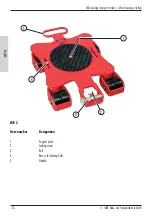
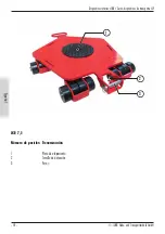
Page 31: ...chnik GmbH JKB revolving transport trolleys JLF multi purpose trolleys 31 English 3 Overview 3 1 JKB revolving transport trolleys JKB 1 5 Item number Designation 1 Support plate 2 Locking screw 3 Bolt...

Page 32: ...und Transporttechnik GmbH JKB revolving transport trolleys JLF multi purpose trolleys 32 English JKB 3 Item number Designation 1 Support plate 2 Locking screw 3 Bolt 4 Recess for lashing belts 5 Handl...

Page 33: ...ttechnik GmbH JKB revolving transport trolleys JLF multi purpose trolleys 33 English JKB 4 Item number Designation 1 Handle 2 Recess for lashing belts 3 Support plate 4 Locking screw 5 Bolt 1 2 3 4 5...

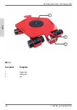
Page 34: ...UNG Hebe und Transporttechnik GmbH JKB revolving transport trolleys JLF multi purpose trolleys 34 English JKB 7 5 Item number Designation 1 Support plate 2 Locking screw 3 Bolt 3 1 2 M P 44A 0059 1 2...

Page 35: ...G Hebe und Transporttechnik GmbH JKB revolving transport trolleys JLF multi purpose trolleys 35 English JKB 7 5 Item number Designation 4 Recess for lashing belts 5 Handle 4 4 5 4 4 M P 44A 0060 4 4 4...

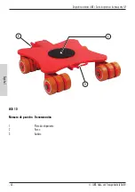
Page 36: ...JUNG Hebe und Transporttechnik GmbH JKB revolving transport trolleys JLF multi purpose trolleys 36 English JKB 10 Item number Designation 1 Support plate 2 Bolt 3 Handle 1 2 3...

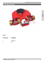
Page 37: ...ebe und Transporttechnik GmbH JKB revolving transport trolleys JLF multi purpose trolleys 37 English JLF 3 5 Item number Designation 1 Locking screw 2 Bolt 2 1 M P 44A 0057 3 2 JLF multi purpose troll...

Page 38: ...JUNG Hebe und Transporttechnik GmbH JKB revolving transport trolleys JLF multi purpose trolleys 38 English JLF 3 5 Item number Designation 3 Support plate 3 M P 44A 0058 3...

Page 39: ...vity before using JUNG revolving transport multi purpose trolleys 4 1 1 Determining the centre of gravity and positioning the transport trolley and lifter DANGER Before a jack is used on the load to b...

Page 40: ...lengths Move the jack so that the load to be lifted is lifted horizontally over the opposite rotating edge Use the jack to raise the load to be lifted to a maximum of 1 mm Determine and record the pr...

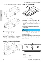
Page 41: ...located for this purpose use the higher of the two pressure values of the parallel sides as the reference value Example sides 1 and 2 300 bar 1000 mm 230 bar 767 mm Example sides 3 and 4 300 bar 1500...

Page 42: ...the opposite side is the axis of rotation The other two opposite sides are prohibited as lifting points within the triangle since here the load to be lifted would tilt The following examples show the...

Page 43: ...n trolley 1 under the transport load Position steering system 2 under the transport load WARNING If positioned incorrectly e g on or near the located line there is a danger of tipping since the fulcru...

Page 44: ...selection of the appropriate transport trolley Ideally the centre of gravity is symmetrical and in the middle of the transport load In this case the selection can be done using the following formula...

Page 45: ...ity of the same transport load is shifted by about 500 mm towards the rear left trolley cassette This increases the effective load to 4800 kg 3 The steering system bears a load of 900 kg 1 while the r...

Page 46: ...e length of the side to be lifted appropriate safety precautions must be taken in order to prevent the load from toppling over This applies in particular to machines in which the centre of gravity is...

Page 47: ...with stable base supports until it is 5 mm above the specified height Due to the danger of tipping avoid large inclinations that can shift the centre of gravity This is particularly a danger for unst...

Page 48: ...e to the desired location DANGER Never lift the load to be lifted on one side up to the ground clearance since there is a big risk of tilting and slipping if this is done WARNING Slowly and carefully...

Page 49: ...e they are subjected to strong friction forces Use commercially available high performance bearing grease Use a brush to grease all bearings Grease the bearings of the trolley at least once a year 5 2...

Page 50: ...the directives of the EC Council 2006 42 EC We herewith declare that the design of the revolving transport and multi purpose trolleys as named above made by JUNG is intended to be connected with other...

Page 51: ...Cuadro sin ptico 55 3 1 Dispositivos rotativos JKB 55 3 2 Servo dispositivos de transporte JLF 61 4 Manejo 63 4 1 Requisitos al lugar de emplazamiento 63 4 1 1 Determinaci n del centro de gravedad y...

Page 52: ...es de seguridad mencionadas Las instrucciones de servicio son parte del producto y por tal motivo se deben guardar En caso de traspasar el producto se deben incluir estas instrucciones de servicio 1 2...

Page 53: ...n recibir regularmente al menos una vez al a o una instrucci n por parte de una per sona capacitada Para ello no es suficiente la entrega o colocar a la vista prescripciones instrucciones de servicio...

Page 54: ...kg 20 Carga kg 1 500 JKB 3 Altura mm 110 Peso kg 37 Carga kg 10 000 JKB 4 Altura mm 110 Peso kg 43 Carga kg 4 000 JKB 6 Altura mm 110 Peso kg 44 Carga kg 6 000 JKB 7 5 Altura mm 110 Peso kg 63 5 Carg...

Page 55: ...ositivos rotativos JKB Servo dispositivos de transporte JLF 55 Espa ol 3 Cuadro sin ptico 3 1 Dispositivos rotativos JKB JKB 1 5 N mero de posici n Denominaci n 1 Plato de alojamiento 2 Tornillo de de...

Page 56: ...k GmbH Dispositivos rotativos JKB Servo dispositivos de transporte JLF 56 Espa ol JKB 3 N mero de posici n Denominaci n 1 Plato de alojamiento 2 Tornillo de detenci n 3 Perno 4 Escotadura para cintas...

Page 57: ...ositivos rotativos JKB Servo dispositivos de transporte JLF 57 Espa ol JKB 4 N mero de posici n Denominaci n 1 Asidero 2 Escotadura para cintas de amarre 3 Plato de alojamiento 4 Tornillo de detenci n...

Page 58: ...ransporttechnik GmbH Dispositivos rotativos JKB Servo dispositivos de transporte JLF 58 Espa ol JKB 7 5 N mero de posici n Denominaci n 1 Plato de alojamiento 2 Tornillo de detenci n 3 Perno 3 1 2 M P...

Page 59: ...Transporttechnik GmbH Dispositivos rotativos JKB Servo dispositivos de transporte JLF 59 Espa ol JKB 7 5 N mero de posici n Denominaci n 4 Escotadura para cintas de amarre 5 Asidero 4 4 5 4 4 M P 44A...

Page 60: ...JUNG Hebe und Transporttechnik GmbH Dispositivos rotativos JKB Servo dispositivos de transporte JLF 60 Espa ol JKB 10 N mero de posici n Denominaci n 1 Plato de alojamiento 2 Perno 3 Asidero 1 2 3...

Page 61: ...ttechnik GmbH Dispositivos rotativos JKB Servo dispositivos de transporte JLF 61 Espa ol JLF 3 5 N mero de posici n Denominaci n 1 Tornillo de detenci n 2 Perno 2 1 M P 44A 0057 3 2 Servo dispositivos...

Page 62: ...JUNG Hebe und Transporttechnik GmbH Dispositivos rotativos JKB Servo dispositivos de transporte JLF 62 Espa ol JLF 3 5 N mero de posici n Denominaci n 3 Plato de alojamiento 3 M P 44A 0058 3...

Page 63: ...ntro de gravedad an tes de utilizar dispositivos rotativo o servo dispositivos de transporte de la empresa JUNG 4 1 1 Determinaci n del centro de gravedad y posicionamiento del dispositivo de transpor...

Page 64: ...anera que el producto a elevar sea elevado horizontalmente por encima del borde de giro opuesto Elevar el producto a elevar como m ximo 1 mm con el aparato de elevaci n Determinar y registrar la presi...

Page 65: ...bas presiones de los lados paralelos como valor de referencia Ejemplo lado 1 y 2 300 bares 1000 mm 230 bares 767 mm Ejemplo lado 3 y 4 300 bares 1500 mm 200 bares 1000 mm Dibujar los resultados En el...

Page 66: ...el lado opuesto es el eje de giro Los otros dos lados opuestos est n prohibidos como puntos de elevaci n dentro del tri ngulo ya que en este caso el producto a elevar volcar a Los siguientes ejemplos...

Page 67: ...icionar el dispositivo de maniobra 2 debajo del producto a transportar ADVERTENCIA En caso de una colocaci n incorrecta p ej sobre o en la proximidad de la l nea determinada existe peligro de vuelco y...

Page 68: ...DVERTENCIA El peso total de la carga a elevar y a desplazar y la posici n del centro de gravedad se deben conocer antes de la operaci n de elevaci n y movimiento Para la selecci n del dispositivo apro...

Page 69: ...se ha desplazado aprox 500 mm en direcci n del m dulo trasero izquierdo del dispositivo Con ello au menta la carga activa a 4800 kg 3 El dispositivo de maniobra soporta una carga de 900 kg 1 y el m du...

Page 70: ...en tomarse medidas apropiadas de seguridad contra el vuelco de la carga Esto es v lido especialmente para las m quinas en las que el centro de gravedad se encuentra en la parte superior de la carga In...

Page 71: ...n apoyos hasta 5 mm sobre la altura especificada Evitar una elevada inclinaci n ya que se genera peligro de vuelco a causa del des plazamiento del centro de gravedad especialmente en productos de tran...

Page 72: ...ca elevar el producto solo por un lado hasta la altura de desplazamiento ya que aqu existe un gran peligro de vuelco y resbalamiento ADVERTENCIA Colocar el producto a transportar lentamente y con cuid...

Page 73: ...ri dicamente los cojinetes puesto que all act an fuerzas de fricci n fuertes Para el engrase utilizar grasa para cojinetes de alto rendimiento de uso comercial Utilizar un pincel para engrasar todos l...

Page 74: ...jo CE 2006 42 CE Por la presente declaramos que el tipo constructivo de los dispositivos rotativos y servo dispositivos de transporte marca JUNG est n determinados para formar otra m quina en combinac...

Page 75: ...es 78 3 Vue d ensemble 79 3 1 Ch ssis gyroscopiques JKB 79 3 2 Ch ssis assist s JLF 85 4 Commande 87 4 1 Exigences requises envers le lieu d installation 87 4 1 1 D terminer le centre de gravit et le...

Page 76: ...particulier des indications de s curit indiqu es Le mode d emploi fait partie int grante du produit et doit donc tre conserv et il doit tre donn en cas de 1 2 Utilisation non conforme la destination L...

Page 77: ...oins une fois par an tre initi e par une personne qualifi e l utilisation des appareils Le sim ple fait de remettre ou accrocher des r glements des instructions de service ou des plaques d avertisseme...

Page 78: ...ge kg 1 500 JKB 3 Hauteur mm 110 Poids kg 37 Charge kg 10 000 JKB 4 Hauteur mm 110 Poids kg 43 Charge kg 4 000 JKB 6 Hauteur mm 110 Poids kg 44 Charge kg 6 000 JKB 7 5 Hauteur mm 110 Poids kg 63 5 Cha...

Page 79: ...chnik GmbH Ch ssis gyroscopiques JKB Ch ssis assist s JLF 79 Fran ais 3 Vue d ensemble 3 1 Ch ssis gyroscopiques JKB JKB 1 5 Num ro de position D signation 1 Plateau de r ception 2 Vis d arr t 3 Boulo...

Page 80: ...und Transporttechnik GmbH Ch ssis gyroscopiques JKB Ch ssis assist s JLF 80 Fran ais JKB 3 Num ro de position D signation 1 Plateau de r ception 2 Vis d arr t 3 Boulon 4 Encoche pour sangles 5 Poign e...

Page 81: ...rttechnik GmbH Ch ssis gyroscopiques JKB Ch ssis assist s JLF 81 Fran ais JKB 4 Num ro de position D signation 1 Poign e 2 Encoche pour sangles 3 Plateau de r ception 4 Vis d arr t 5 Boulon 1 2 3 4 5...

Page 82: ...Hebe und Transporttechnik GmbH Ch ssis gyroscopiques JKB Ch ssis assist s JLF 82 Fran ais JKB 7 5 Num ro de position D signation 1 Plateau de r ception 2 Vis d arr t 3 Boulon 3 1 2 M P 44A 0059 1 2 3...

Page 83: ...Hebe und Transporttechnik GmbH Ch ssis gyroscopiques JKB Ch ssis assist s JLF 83 Fran ais JKB 7 5 Num ro de position D signation 4 Encoche pour sangles 5 Poign e 4 4 5 4 4 M P 44A 0060 4 4 4 4 5 4 4...

Page 84: ...JUNG Hebe und Transporttechnik GmbH Ch ssis gyroscopiques JKB Ch ssis assist s JLF 84 Fran ais JKB 10 Num ro de position D signation 1 Plateau de r ception 2 Boulon 3 Poign e 1 2 3...

Page 85: ...UNG Hebe und Transporttechnik GmbH Ch ssis gyroscopiques JKB Ch ssis assist s JLF 85 Fran ais JLF 3 5 Num ro de position D signation 1 Vis d arr t 2 Boulon 2 1 M P 44A 0057 3 2 Ch ssis assist s JLF 1...

Page 86: ...JUNG Hebe und Transporttechnik GmbH Ch ssis gyroscopiques JKB Ch ssis assist s JLF 86 Fran ais JLF 3 5 Num ro de position D signation 3 Plateau de r ception 3 M P 44A 0058 3...

Page 87: ...oquant des accidents pouvant tre mortels Veillez toujours d terminer le centre de gravit avant d utiliser des ch ssis gyrosco piques ou ch ssis assist s JUNG 4 1 1 D terminer le centre de gravit et le...

Page 88: ...chandise soit soulev e l horizontale via l axe de rotation oppos Avec l appareil de levage soulever la marchandise d 1 mm maximum D terminer de la m me mani re la pression sur chacun des quatre c t s...

Page 89: ...comme valeur de r f rence la valeur de pression la plus lev e des deux des c t s parall les Exemple c t 1 et 2 300 bar 1000 mm 230 bar 767 mm Exemple c t 3 et 4 300 bar 1500 mm 200 bar 1000 mm Dessine...

Page 90: ...stitue l axe de rotation Les deux autres c t s oppos s sont interdits comme points de levage l int rieur du triangle vu que la marchandise pourrait alors basculer Les exemples suivants montrent commen...

Page 91: ...chandise ATTENTION En cas de mauvaise fixation par ex sur ou proximit de la ligne localis e il y a un risque de bascule car l axe de rotation peut se d placer La marchandise bascule de mani re incontr...

Page 92: ...ids total de la charge soulever et d placer ainsi que la position du centre de gravit doivent tre connus avant de commencer soulever ou d placer Pour choisir le ch ssis de transport ad quat il faut d...

Page 93: ...archandise est d cal d environ 500 mm vers la cassette arri re gauche du ch ssis de transport Ce qui augmente sa charge appliqu e de 4 800 kg 3 Le syst me de guidage supporte une charge de 900 kg 1 et...

Page 94: ...la longueur du c t soulever prendre des mesures appropri es de s curisation pour emp cher la charge de basculer Cela s applique en particulier aux machines dont le centre de gravit se situe dans la mo...

Page 95: ...liser jusqu 5 mm au dessus de la hauteur sp cifi e vitez les fortes inclinaisons sous peine de basculement en raison du d calage du centre de gravit surtout si la charge transport e n est pas tr s sta...

Page 96: ...traction DANGER Ne jamais soulever la marchandise de mani re unila t rale jusqu la hauteur libre en raison d un risque norme de basculement et de d rapage ATTENTION Avec pr caution lentement d poser...

Page 97: ...que les forces de frottement agissent le plus Utiliser cet effet de la graisse haute performance que l on trouve habituellement dans le commerce Utiliser un pinceau pour graisser chaque palier Graisse...

Page 98: ...du conseil de l UE 2006 42 CE Par la pr sente nous d clarons que le type de construction des ch ssis gyroscopiques et ch ssis assist s comme d nomm s ci dessus de la marque JUNG est destin combiner d...

Page 99: ...103 3 1 Carrelli giroscopici JKB 103 3 2 Servocarrelli JLF 109 4 Impiego 111 4 1 Requisiti per il luogo di installazione 111 4 1 1 1 Determinazione del baricentro e posizionamento del carrello di tra...

Page 100: ...uale in particolare i citati avvisi di sicurezza Le istruzioni per l uso sono parte integ rante del prodotto e devono essere perci conservate e trasmesse al momento della cessione del prodotto 1 2 Imp...

Page 101: ...truito a regolari intervalli di tempo almeno una volta l anno da parte di una persona autorizzata Non basta al riguardo la sola consegna od esposizione di norme istruzioni per l uso o cartelli di avvi...

Page 102: ...g 37 Capacit di carico kg 10 000 JKB 4 Altezza mm 110 Peso kg 43 Capacit di carico kg 4 000 JKB 6 Altezza mm 110 Peso kg 44 Capacit di carico kg 6 000 JKB 7 5 Altezza mm 110 Peso kg 63 5 Capacit di ca...

Page 103: ...technik GmbH Carrelli giroscopici JKB Servocarrelli JLF 103 Italiano 3 Prospetto 3 1 Carrelli giroscopici JKB JKB 1 5 Numero di posizione Denominazione 1 Piatto di appoggio 2 Vite di arresto 3 Perno 2...

Page 104: ...JUNG Hebe und Transporttechnik GmbH Carrelli giroscopici JKB Servocarrelli JLF 104 Italiano JKB 3 Numero di posizione Denominazione 1 Piatto di appoggio 2 Vite di arresto 3 Perno 3 2 1 4 5...

Page 105: ...H Carrelli giroscopici JKB Servocarrelli JLF 105 Italiano JKB 4 Numero di posizione Denominazione 1 Maniglia 2 Alloggiamento per cinghie di stabilizzazione 3 Piatto di appoggio 4 Vite di arresto 5 Per...

Page 106: ...NG Hebe und Transporttechnik GmbH Carrelli giroscopici JKB Servocarrelli JLF 106 Italiano JKB 7 5 Numero di posizione Denominazione 1 Piatto di appoggio 2 Vite di arresto 3 Perno 3 1 2 M P 44A 0059 1...

Page 107: ...d Transporttechnik GmbH Carrelli giroscopici JKB Servocarrelli JLF 107 Italiano JKB 7 5 Numero di posizione Denominazione 4 Alloggiamento per cinghie di stabilizzazione 5 Maniglia 4 4 5 4 4 M P 44A 00...

Page 108: ...JUNG Hebe und Transporttechnik GmbH Carrelli giroscopici JKB Servocarrelli JLF 108 Italiano JKB 10 Numero di posizione Denominazione 1 Piatto di appoggio 2 Perno 3 Maniglia 1 2 3...

Page 109: ...UNG Hebe und Transporttechnik GmbH Carrelli giroscopici JKB Servocarrelli JLF 109 Italiano JLF 3 5 Numero di posizione Denominazione 1 Vite di arresto 2 Perno 2 1 M P 44A 0057 3 2 Servocarrelli JLF 1...

Page 110: ...JUNG Hebe und Transporttechnik GmbH Carrelli giroscopici JKB Servocarrelli JLF 110 Italiano JLF 3 5 Numero di posizione Denominazione 3 Piatto di appoggio 3 M P 44A 0058 3...

Page 111: ...corpo anche incidenti di natura mortale in seguito ad un ribaltamento o scivolamento Prima di usare i carrelli giroscopici o i servocarrelli JUNG l operatore deve sempre determinare il baricentro 4 1...

Page 112: ...carico venga sollevato orizzontalmente rispetto al bordo di rotazi one contrapposto Con il sollevatore sollevare il carico di 1 mm al massimo Determinare la pressione nel medesimo modo su tutti e quat...

Page 113: ...l maggiore dei due valori di pressione sui lati paralleli Esempio per lato 1 e 2 300 bar 1000 mm 230 bar 767 mm Esempio per lato 3 e 4 300 bar 1500 mm 200 bar 1000 mm Riportare i risultati nel disegno...

Page 114: ...uisce l asse di rotazione Gli altri due lati opposti sono vietati come punto di sollevamento all interno del triangolo poich il carico da sollevare si ribalterebbe Gli esempi successivi illustrano com...

Page 115: ...are AVVERTENZA Nel caso di erronea applicazione per es sulla linea o nelle vicinanze della linea individuata esiste il pericolo di ribaltamento perch il bordo di rotazione si pu spostare Il carico si...

Page 116: ...del carico da sollevare e da mo vimentare e la posizione del baricentro devono essere noti prima di iniziare l operazione di sollevamento e movimentazione Per la scelta del carrello adeguato deve esse...

Page 117: ...re sposta to di circa 500 mm in direzione del cassetto posteriore sinistro delcarrello giroscopico Ci incrementa il carico applicato a 4800 kg 3 Il gruppo di sterzata sostiene un peso di 900 kg 1 e il...

Page 118: ...Ci vale in particolare per le macchine in cui il baricentro si trova nella met superiore del carico L operatore deve informarsi sulle dimensioni del carico da trasportare e deve determinare la posizi...

Page 119: ...di sotto substrati di appoggio fino a 5 mm sopra l altezza indicata Evitare forti inclinazioni poich sussiste il pericolo di ribaltamento a causa dello spostamento del baricentro in particolare se il...

Page 120: ...vare mai da un solo lato il carico fino all altezza utile a posizionarvi sotto il trasportatore perch persiste un enorme rischio di ribaltamento e di scivolamento AVVERTENZA Abbassare lentamente e con...

Page 121: ...la lubrificazione utilizzare grasso per cuscinetti per alte prestazioni comunemente reperibile sul mercato Per lubrificare tutti i cuscinetti utilizzare un pennello Lubrificare con grasso almeno una v...

Page 122: ...siglio della CE 2006 42 CE Con questo documento dichiariamo che il tipo di costruzione dei carrelli giroscopici come sopra denominato di fa bbricazione JUNG destinato a costituire una macchina mediant...

Page 123: ...hnische gegevens 126 3 Overzicht 127 3 1 Draaibare onderstellen JKB 127 3 2 Servo onderstellen JLF 133 4 Bediening 135 4 1 Eisen aan de opstellingsplaats 135 4 1 1 Bepaling van het zwaartepunt en posi...

Page 124: ...nwijzing is een bestanddeel van het product en moet daarom worden bewaard en bij het doorgeven van het product worden meegegeven 1 2 Oneigenlijk gebruik De onderstellen zijn niet bestemd voor het tran...

Page 125: ...deze toestellen moeten regelmatig maar minstens n keer per jaar door een gekwalificeerde persoon worden geschoold Het louter overhandigen of uithangen van voorschriften gebruiksaanwijzingen of waarsc...

Page 126: ...KB 3 Hoogte mm 110 Gewicht kg 37 Draaglast kg 10 000 JKB 4 Hoogte mm 110 Gewicht kg 43 Draaglast kg 4 000 JKB 6 Hoogte mm 110 Gewicht kg 44 Draaglast kg 6 000 JKB 7 5 Hoogte mm 110 Gewicht kg 63 5 Dra...

Page 127: ...ttechnik GmbH Draaibare onderstellen JKB Servo onderstellen JLF 127 Nederlands 3 Overzicht 3 1 Draaibare onderstellen JKB JKB 1 5 Positienummer Benaming 1 Opnameschijf 2 Arretierungsschraube 3 Bout 2...

Page 128: ...JUNG Hebe und Transporttechnik GmbH Draaibare onderstellen JKB Servo onderstellen JLF 128 Nederlands JKB 3 Positienummer Benaming 1 Opnameschijf 2 Grendelschroef 3 Bout 3 2 1 4 5...

Page 129: ...rttechnik GmbH Draaibare onderstellen JKB Servo onderstellen JLF 129 Nederlands JKB 4 Positienummer Benaming 1 Handgreep 2 Uitsparing voor spanriemen 3 Opnameschijf 4 Grendelschroef 5 Bout 1 2 3 4 5 M...

Page 130: ...JUNG Hebe und Transporttechnik GmbH Draaibare onderstellen JKB Servo onderstellen JLF 130 Nederlands JKB 7 5 Positienummer Benaming 1 Opnameschijf 2 Grendelschroef 3 Bout 3 1 2 M P 44A 0059 1 2 3...

Page 131: ...NG Hebe und Transporttechnik GmbH Draaibare onderstellen JKB Servo onderstellen JLF 131 Nederlands JKB 7 5 Positienummer Benaming 4 Uitsparing voor spanriemen 5 Handgreep 4 4 5 4 4 M P 44A 0060 4 4 4...

Page 132: ...JUNG Hebe und Transporttechnik GmbH Draaibare onderstellen JKB Servo onderstellen JLF 132 Nederlands JKB 10 Positienummer Benaming 1 Opnameschijf 2 Bout 3 Handgreep 1 2 3...

Page 133: ...UNG Hebe und Transporttechnik GmbH Draaibare onderstellen JKB Servo onderstellen JLF 133 Nederlands JLF 3 5 Positienummer Benaming 1 Grendelschroef 2 Bout 2 1 M P 44A 0057 3 2 Servo onderstellen JLF 1...

Page 134: ...JUNG Hebe und Transporttechnik GmbH Draaibare onderstellen JKB Servo onderstellen JLF 134 Nederlands JLF 3 5 Positienummer Benaming 3 Opnameschijf 3 M P 44A 0058 3...

Page 135: ...staan Bepaal altijd het zwaartepunt voordat u draaibare onderstellen en servo onderstellen van JUNG gebruikt 4 1 1 Bepaling van het zwaartepunt en positionering van transportonderstel en heftoestel GE...

Page 136: ...el zodanig verschuiven dat de heflast via de tegenoverliggende draaikant horizontaal wordt opgeheven De heflast maximaal 1 mm met het heftoestel opheffen Aan de vier zijden op dezelfde manier de druk...

Page 137: ...moet respectievelijk de hoogste van de twee drukwaarden van de paral lelle zijden worden gebruikt als referentiewaarde Voorbeeld zijde 1 en 2 300 bar 1000 mm 230 bar 767 mm Voorbeeld zijde 3 en 4 300...

Page 138: ...trokken Dat heeft tot gevolg dat de tegenoverliggende zijde de draaias is De andere beide tegenoverliggende zijden zijn binnen de driehoek verboden als hefpunten aangezien de heflast hier zou kantele...

Page 139: ...et onder de transportlast worden gepositioneerd WAARSCHUWING Let op Bij een foutieve bevestiging bijv op of in de buurt van de vastgelegde lijn bestaat er kantelgevaar aangezien de draaikant kan versc...

Page 140: ...op te heffen en te transport eren last en de positie van het zwaartepunt moeten v r het hef en transportproces bekend zijn Voor de keuze van het geschikte onderstel moeten het zwaartepunt en het tota...

Page 141: ...veer 500 mm in de richting van de onderstelcas sette links achteraan verschoven Daardoor wordt de inwerkende belasting verhoogd tot 4800 kg 3 De stuurinrichting draagt een last van 900 kg 1 en de rech...

Page 142: ...offen tegen het kantelen van de last Dit geldt in het bijzonder bij machines waarbij het zwaartepunt zich in de bovenste helft van de last bevindt Informeer u over de afmetingen van de transportlast e...

Page 143: ...rsteund Grote hellingshoeken moeten worden vermeden aangezien er kantelgevaar bestaat door een verschuiving van het zwaartepunt in het bijzonder bij een labiele transportlast Twee dezelfde onderstelle...

Page 144: ...wenste locatie worden vervoerd GEVAAR De heflast mag nooit eenzijdig worden opgeheven tot op de hoogte waar men onder kan rijden omdat hier enorme kantel en slipgevaren bestaan WAARSCHUWING De transpo...

Page 145: ...matig worden ingevet aangezien daar sterke wrijvingskrachten inwerken Voor het invetten moet in de handel verkrijgbaar lagervet voor zware toepassingen worden gebruikt Gebruik voor het invetten van al...

Page 146: ...len zoals hierboven vermeld van het merk JUNG bestemd is om met andere machines te worden verbonden tot n machine De ingebruikneming is verboden totdat werd vastgesteld dat de machine waarmee n van de...

Page 147: ...Notizen Notes Notas Notes Note Aantekeningen...

Page 148: ...behalten wir uns vor Made in Germany 03 2018 Printed in Germany www jung hebetechnik de Our logo and brand name JUNG are registered as trademarks in the EU US and China with register numbers EU logo...

Reviews: