5 F
unctions
19
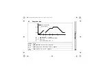
5.3
Controller
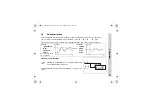
Controller structure
The controller structure is defined via the parameters
Pb
,
dt
and
rt
.
Example: Setting for PI controller
→
Pb .1
=120,
dt
=0sec,
rt
=350sec
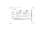
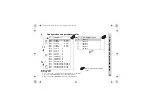
Symbol
Notes
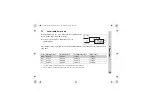
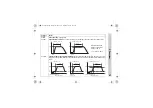
C113
Controller type and assignment of the controller outputs to the physical
outputs 1+2
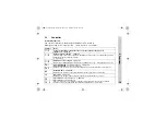
C116
Outputs in fault condition
The switching states of the outputs are defined here in the event of over/underrange, probe
break/short circuit or display overflow.
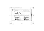
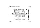
v
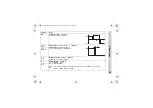
C118
Assignment of the outputs
Only for Type 702042/43/44; overwrites the assignment of
C113
(controller type as
C113
)
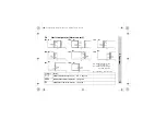
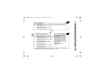
Pb:1
Proportional band 1 (controller output 1)
Proportional band 2 (controller output 2)
Influences the P action of the controller. If
Pb
=0, the controller structure is not effective.
Pb:2
dt
Influences the D action of the controller. If
dt
=0, the controller has no D action.
rt
Influences the I action of the controller. If
rt
=0, the controller has no I action.
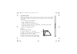
Cy 1
Cycle time 1 (controller output 1)
Cycle time 2 (controller output 2)
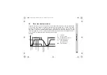
The cycle time has to be selected so that the energy supply to the process is virtually
continuous, while not subjecting the switching elements to excessive wear.
Cy 2
b70.2040en.bk Seite 19 Mittwoch, 19. November 2008 10:15 10


