


– –
1. SPECIFICATIONS
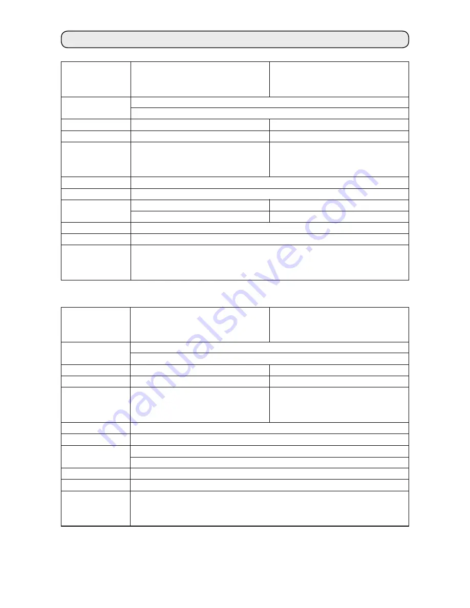
Model name
Application
Hook
Thread trimmer
Separately
driven needle bar
mechanism
Max. sewing speed
Needle
Gauge size
Lift of presser foot
Lubrication
Noise
LH-3528
LH-3528-7
(with automatic thread trimmer)
For light- and medium-weight materials
S type : standard,F type : foundation, A type : light-weight materials, G type : jeans
Small hook
Not provided
Not provided
Small hook
Provided
Not provided
3,000 rpm
DP x 5 #9 to #6 (For F,A and S types), DP x 5 #6 to #22 (G type)
3/32" to -/2"
2.4 to 38. mm
/8" to -/4"
3.2 to 3.8 mm
2 mm by knee lifter, 5.5 mm by hand lifter lever
JUKI NEW DEFRIX OIL No. or JUKI MACHINE OIL #7
Workplace-related noise at sewing speed
n = 2,700 min
–
: L
pa
≦
85 dB(A)
Noise measurement according to DIN 45635-48-A-.
Model name
Application
Hook
Thread trimmer
Separately
driven needle bar
mechanism
Max. sewing speed
Needle
Gauge size
Lift of presser foot
Lubrication
Noise
LH-3568
(with incorporating corner stitching)
LH-3568-7
(with automatic thread trimmer
incorporating corner stitching)
For light- and medium-weight materials
S type : standard, G type : jeans
Small hook
Not provided
Provided
Small hook
Provided
Provided
3,000 rpm
DP x 5 #9 to #6 (S type), DP x 5 #6 to #22 (G type)
/8" to 3/4"
3.2 to 9. mm
2 mm by knee lifter, 5.5 mm by hand lifter lever
JUKI NEW DEFRIX OIL No. or JUKI MACHINE OIL #7
Workplace-related noise at sewing speed
n = 2,600 min
–
: L
pa
≦
85 dB(A)
Noise measurement according to DIN 45635-48-A-.