JUKI KE-2070 Manual Download Page 29

            KE-2070/2080 MS 

Parameter                                   

3-3. Origin 

rough 

adjustment 

3-3-1. Function 

Perform teaching so that the 1st mark of the calibration block is located at the center of the 

OCC during home position return. 

3-3-2. Required 

jig 

This setup requires no jigs. 

3-3-3. Operation 

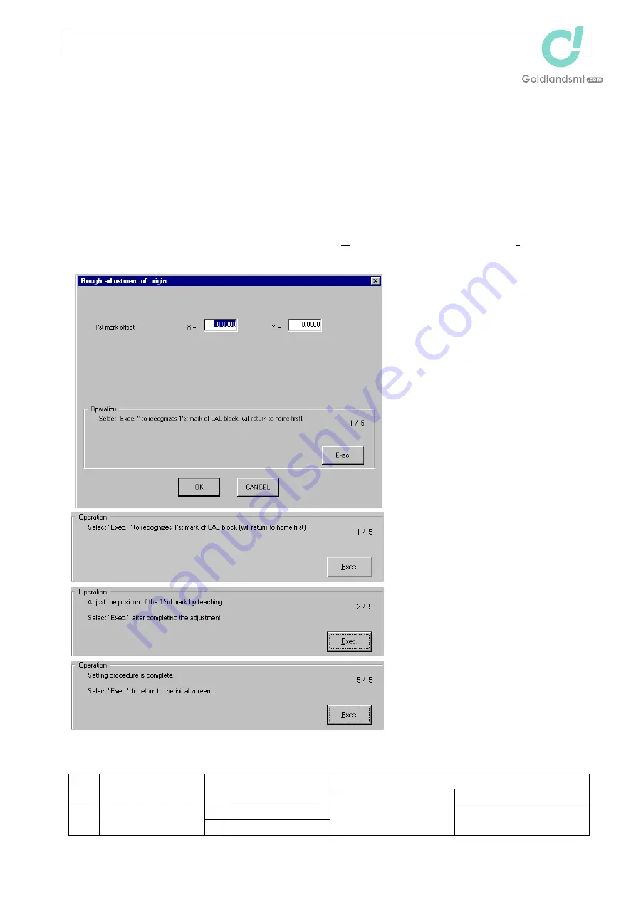
If you select [Rough adjustment of origin (R)...] from the [Initial set-up (I)] menu, the 

following [Rough adjustment of origin] dialog box will appear. 

<Screen 1/5> 

Select [Exec.] when ready. 

When [Exec.] is selected, the OCC is 
moved to the 1st mark of the CAL 
block and the mark is recognized after 
the home position return has been 
completed. 
According to the recognition results, 
the offset to the design value is 
displayed. 
If an error occurs during recognition 
of the mark, the offset display is 
cleared. 

<Screen 2/5> 

Using the teaching function, adjust 

the CAL block position while 
checking the OCC monitor so that 
the 1st mark is located around the 
center of the vision field.  (Even 
though there are no changes, you 
must enter the teaching mode once.) 

<Screen 5/5> 

The setting is then completed. 

Select [Exec.] to return to the initial 

operation screen. 

If you select [OK], the confirmation 

message box is shown, and then the normal home position return (with recognition of the 1st 

mark of the CAL block) is performed. 

MSP value is incorrect. 

No. Item 

MSP 

allowable 

value 

Faulty part 

Adjustment (check) item 

2.0 to 4.0 mm 

First mark offset 

1.0 to 5.0 mm 

Home position return 

inoperable 


3-5 

Rev. 1.00


Summary of Contents for KE-2070

Page 1: ...High Speed Flexible Mounter KE 2070 KE 2080 MS PARAMETER JUKI CORPORATION SMT CENTER CUSTOMER SERVICE DEPT ELECTRONIC ASSEMBLY TEST SYSTEMS DIV...

Page 2: ...as carefully as possible However if you have a question or find a mistake or missing information contact our dealers or JUKI Corp 4 JUKI Corp is not responsible for any defects or malfunction due to y...

Page 3: ...r make sure that no work personnel exist inside the machine Before turning ON the power make sure that no objects such as adjustment tools hindering any operation inside the machine are mounted or pla...

Page 4: ...ns 3 1 3 2 Square adjustment 3 2 3 3 Origin rough adjustment 3 5 3 4 XY axis correction coefficient 3 6 3 5 Options 3 7 3 6 Action specifications 3 9 3 7 X axis curve correction 3 14 3 8 Comment 3 15...

Page 5: ...cuum calibration 4 67 5 Upgrade 5 1 5 1 VCS 5 1 5 2 I O 5 2 5 3 B F 5 3 5 4 LNC60 5 4 5 5 Servo Amp 5 5 6 Delete software 6 1 6 1 I O 6 1 6 2 B F 6 2 6 3 JVS 6 3 7 Others 7 1 7 1 CAL piece holder 7 1...

Page 6: ...d and the action motion specifications Offset set up that records errors to the design values during assembly and Upgrade that upgrades the operation software after replacement of the control board an...

Page 7: ...menu e The MS parameter initial screen will appear f To exit the MS parameter click the X mark at the upper right corner of the MS parameter initial screen Or select Exit from the File menu or click...

Page 8: ...KE 2070 2080 MS Parameter 1 3 Rev 1 00...

Page 9: ...icted as the head is moved smoothly 1 3 Configuration The MS parameter operation menu is classified into three groups Initial set up Offset set up and Others Initial set up This setup is used when ins...

Page 10: ...s OPT2070S DAT Information on optional units and optional operations POS2070S DAT Assembly dimensions related to mechanical units of the machine SUP2070S DAT Machine setup information Additionally bac...

Page 11: ...KE 2070 2080 MS Parameter e Select the save destination and then click Next f Check the contents to be saved and the save destination and then click Next g Select Action 1 6 Rev 1 00...

Page 12: ...KE 2070 2080 MS Parameter h The progress status is displayed When the backup is completed the following screen will appear Select Finish i The following file has been created 1 7 Rev 1 00...

Page 13: ...up file follow the steps below c Select Control Data Management from the File F menu d The Control data files storage wizard will appear In this window check on 4 Restore control data from disk and cl...

Page 14: ...in Restoring origin check that the device set in Restoration end is correct and then click Next g Select Action h The progress status is displayed When the backup file is restored completely the follo...

Page 15: ...c Select Control Data Management from the File F menu d The Control data files storage wizard will appear In this window check on 1 Backup control data to flash memory and click Next e Check the cont...

Page 16: ...KE 2070 2080 MS Parameter f Select Action g The progress status is displayed When the backup is completed the following screen will appear Select Finish 1 11 Rev 1 00...

Page 17: ...w c Select Control Data Management from the File F menu d The Control data files storage wizard will appear In this window check on 3 Restore control data from flash memory and click Next N 1 12 e Sel...

Page 18: ...KE 2070 2080 MS Parameter f Select Action g The progress status is displayed When the backup is completed the following screen will appear Select Finish 1 13 Rev 1 00...

Page 19: ...n only data is changed this change is not valid Pay special attention to this point Additionally if you select Cancel the changes you have made become invalid 1 5 2 Limitations The ORIGIN switch is in...

Page 20: ...it You cannot select a menu corresponding to the units set as not mounted in Options O of Initial set up I 2 2 Menu contents KE2070 2080 Note 1 All heads All heads 1st mark of CAL block is recognized...

Page 21: ...center of the OCC will move to the selected position If you select Optional pos the following XY moves to a given coordinate dialog box will appear Input coordinates in the Moving target position fiel...

Page 22: ...on not in use Press the Alt and keys at the same time The following list will appear KE 2070 KE 2080 Input a coordinate in the Moving target position field and select the MOVE button or press the F3...

Page 23: ...control 2 6 Light map If you select Light map L from the control menu the following Light map control dialog box will appear Select a direction and input a line No and then select the Exec button or p...

Page 24: ...e lit checked off If you select OK the VCS lights are lit with set contents when selecting the VCS illumination control next time If you select CANCEL the set contents become invalid 2 8 Nozzle up cyl...

Page 25: ...tion Settings for optional machine types 3 1 2 Required jig This setup requires no jigs 3 1 3 Operation If you select Mech specifications C from the Initial set up I menu the following Conveyor specif...

Page 26: ...etails about support table offset see Chapter 4 Offset set up described in a later part of this manual If you select Adjust square G from the Initial set up I menu the following Adjust square dialog b...

Page 27: ...setting processes are completed Select Exec to return to the initial operation screen If the value of Magnet SW adjustment which has been obtained automatically is beyond a range of 0 08mm to 0 08mm a...

Page 28: ...letion of the operation press the OK button and the left screen will appear Selecting Yes will automatically set up the parameter for the Correction coefficient of XY axis stated in section 3 4 XY axi...

Page 29: ...results the offset to the design value is displayed If an error occurs during recognition of the mark the offset display is cleared Screen 2 5 Using the teaching function adjust the CAL block position...

Page 30: ...ed only when JUKI instructs to change the settings 3 4 2 Required jig This setup requires no jigs 3 4 3 Operation If you select Correction coefficient of XY axis X from the Initial set up I menu the f...

Reviews: