JUKI DSC-245 Instruction Manual Download Page 6

iv

iv

5. Be sure to turn the power off and check to be sure that the machine and motor completely stop before re-

moving the belt cover and V-belt in order to prevent accident caused by abrupt start of the machine or motor.

6. If a servomotor is used with the machine, the motor does not produce noise while the machine is at rest.

Be sure not to forget to turn the power off in order to prevent accident caused by abrupt start of the motor.

7. Never use the machine with the cooling opening of the motor power box shielded in order to prevent fire

accident by overheat.

Lubrication

1. Be sure to use JUKI genuine oil and JUKI genuine grease to the parts to be lubricated.

2. If the oil adheres on your eye or body, be sure to immediately wash it off in order to prevent inflamma-

tion or irritation.

3. If the oil is swallowed unintentionally, be sure to immediately consult a medical doctor in order to pre-

vent diarrhea or vomiting.

Maintenance

1. In prevention of accident caused by unfamiliarity with the machine, repair and adjustment has to be

carried out by a service technician who is thoroughly familiar with the machine within the scope defined

in the instruction manual. Be sure to use JUKI genuine parts when replacing any of the machine parts.

JUKI assumes no responsibility for any accident caused by improper repair or adjustment or the use of

any part other than JUKI genuine one.

2. In prevention of accident caused by unfamiliarity with the machine or electrical-shock accident, be sure

to ask an electrical technician of your company or JUKI or distributor in your area for repair and mainte-

nance (including wiring) of electrical components.

3. When carrying out repair or maintenance of the machine which uses air-driven parts such as an air cyl-

inder, be sure to remove the air supply pipe to expel air remaining in the machine beforehand, in order to

prevent accident caused by abrupt start of the air-driven parts.

4. Be sure to check that screws and nuts are free from looseness after completion of repair, adjustment

and part replacement.

5. Be sure to periodically clean up the machine during its duration of use. Be sure to turn the power off

and verify that the machine and motor stop completely before cleaning the machine in order to prevent

accident caused by abrupt start of the machine or motor.

6. Be sure to turn the power off and verify that the machine and motor stop completely before carrying out

maintenance, inspection or repair of the machine. (For the machine with a clutch motor, the motor will

keep running for a while by inertia even after turning the power off. So, be careful.)

7. If the machine cannot be normally operated after repair or adjustment, immediately stop operation and

contact JUKI or the distributor in your area for repair in order to prevent accident that can result in per-

sonal injury or death.

8. If the fuse has blown, be sure to turn the power off and eliminate the cause of blowing of the fuse and

replace the blown fuse with a new one in order to prevent accident that can result in personal injury or

death.

9. Be sure to periodically clean up the air vent of the fan and inspect the area around the wiring in order to

prevent fire accident of the motor.

Operating environment

1. Be sure to use the machine under the environment which is not affected by strong noise source (electro-

magnetic waves) such as a high-frequency welder in order to prevent accident caused by malfunction of

the machine.

2. Never operate the machine in any place where the voltage fluctuates by more than "rated voltage ±10 %"

in order to prevent accident caused by malfunction of the machine.

3. Be sure to verify that the air-driven device such as an air cylinder operates at the specified air pressure

before using it in order to prevent accident caused by malfunction of the machine.

4. To use the machine with safety, be sure to use it under the environment which satisfies the following

conditions:

Ambient temperature during operation 

5°C to 35°C

Relative humidity during operation 

35 % to 85 %

5. Dew condensation can occur if bringing the machine suddenly from a cold environment to a warm one.

So, be sure to turn the power on after having waited for a sufficient period of time until there is no sign

of water droplet in order to prevent accident caused by breakage or malfunction of the electrical compo-

nents.

6. Be sure to stop operation when lightning flashes for the sake of safety and remove the power plug in

order to prevent accident caused by breakage or malfunction of the electrical components.

7. Depending on the radio wave signal condition, the machine may generate noise in the TV or radio. If this

occurs, use the TV or radio with kept well away from the machine.

8. In order to ensure the work environment, local laws and regulations in the country where the sewing

machine is installed shall be followed.

In the case the noise control is necessary, an ear protector or other protective gear should be worn ac-

cording to the applicable laws and regulations.

9. Disposal of products and packages and treatment of used lubricating oil should be carried out properly

according to the relevant laws of the country in which the sewing machine is used.

– 17 –

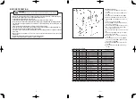
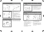
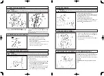
2. Installation process

1) Fit spring 

 over screw 

. In this state, fix

feed bar hinge stud 

.

2) Attach feed driving pin 

 in place.

3) Attach feed bar block A 

 on feed bar oscil-

lating arm 

.

4) Attach feed bar block shaft 

 on feed bar 

.

5) Attach feed bar block B 

 in feed bar block

shaft 

 using E ring 

.

6) Attach feed 

 on feed bar 

 with feed set-

screw 

.

7) Attach feed bar block shaft 

 and feed bar


on which feed 

 has been attached in place

on feed bar hinge stud 

.

8) Install spring support shaft 

 in place.

9) Tighten feed setscrew 

 to allow the needle

to come just at the center of the needle hole

in the feed 

.

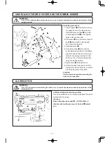
10) Top cover spring 

 of the bed,feed bar shaft

cover 

 and screw 

 of the feed bar shaft

cover 

 in place.

11) Fix top cover 

 of the bed by tightening

screw 

 in the top cover of the bed.

12) Attach throat plate 

 in place and fix it using

screw 

 of the throat plate.

13) Install presser foot (asm.) 

 and walking foot

 in place.

(Caution)

1

The parts attached with an asterisk ( * ) are the exclusive parts for the DSC-245V-4 or -7.

2

The feed driving pin has engraved marker lines. Use the pin which has many marker lines to raise the feed dog,or 

use the pin with less marker lines to lower it.

Note

No.

Part No.

Part Name

Q'ty

Remarks

22

B15242450A0

Presser foot (asm.)

1

23

B1470245000

Walking foot

1

24

SS2110915SP

Screw in throat plate

2

11/64 40 thread ridges, L=8.5

25

B1105245000

Throat plate

1

*

D1105245E00

Throat plate

1

26

SS2090710TP

Screw in top cover of bed

1

9/64 40 thread ridges, L=7

27

B1173245000

Top cover of bed

1

*

D1173245E00

Top cover of bed

1

28

B1175245000

Spring of top cover of bed

1

29

B1613245000

Feed

1

*

D1613245E0A

Feed

1

30

B1645245000

Feed bar block

1

31

RE0300000K0

E ring

1

32

B1644245000

Feed bar block B

1

33

B1643145000

Feed bar block A

1

34

B163224500C

Feed driving pin

1

Selective part (caution 2)

35

B1641245000

Feed bar hinge stud screw

2

36

B1642245000

Feed bar hinge stud screw spring

2

List of parts to be replaced

Part No.

B163224500A

B163224500B

B163224500C

B163224500D

B163224500E

Length(mm)

5.7±0.05

5.9±0.05

6.1±0.05

6.3±0.05

6.5±0.05

Number of marker lines

1

2

3

4

5

Summary of Contents for DSC-245

Page 1: ...No 02 40092228 INSTRUCTION MANUAL DSC 245 4 7 DSC 245V 4 7 NOTE Read safety instructions carefully and understand them before using Retain this Instruction Manual for future reference ...

Page 2: ...日本語 ...

Page 3: ...on is given where there is an immediate danger of death or serous injury if the person in charge or any third party mishandles the machine or does not avoid the dangerous situation when operating or maintaining the machine WARNING This indication is given where there is a potentiality for death or serious injury if the person in charge or any third party mishandles the machine or does not avoid th...

Page 4: ...s out The thread path needle point hook point or bobbin case positioning finger has scratches Remove the scratches on the hook point using a fine sand paper Buff the bobbin case positioning finger The needle thread tension is too high Properly adjust the needle thread tension The needle hits the hook point See 17 NEEDLE TO HOOK RELATIONSHIP Lubrication to hook is inadequate Properly adjust the lub...

Page 5: ...onnector section III Grounding 1 Be sure to have an electrical expert install an appropriate power plug in order to prevent accident caused by earth leakage or dielectric strength voltage fault In addition be sure to connect the power plug to the grounded outlet without exceptions 2 Be sure to ground the earth cable in order to prevent accident caused by earth leakage IV Motor 1 Be sure to use the...

Page 6: ...ore than rated voltage 10 in order to prevent accident caused by malfunction of the machine 3 Be sure to verify that the air driven device such as an air cylinder operates at the specified air pressure before using it in order to prevent accident caused by malfunction of the machine 4 To use the machine with safety be sure to use it under the environment which satisfies the following conditions Am...

Page 7: ...le accidents due to abrupt start of the machine be sure to turn OFF the power to the machine 8 Be careful of handling this product so as not to pour water or oil shock by dropping and the like since this product is a precision instrument 9 When tilting or returning the sewing machine to the home position hold the upper side of the machine head with both hands and perform the work quietly so that f...

Page 8: ...tape MAQ09509000 Feed 1 For attaching a broad tape 23 MAQ09202000 Bed top cover 1 MAQ09402000 Bed top cover 1 24 MAQ09204000 Binder setscrew 2 11 64 threads 40 25 MAQ09205000 Binder lock nut 2 11 64 threads 40 26 MAQ09206000 Tape guide 1 27 SS7110510SP Tape guide setscrew 1 11 64 threads 40 L 5 28 MAQ09203000 Bed top cover spring 1 29 MAQ09201000 Throat plate 1 MAQ09401000 Throat plate 1 30 SS2110...

Page 9: ...e technical documentation and 3 To be prepared with the above technical documentation compiled in accordance with part B of Annex VII and 4 Also to conform to the RoHS Directive 2011 65 EU 5 Relevant information on which should be transmitted in response to a reasoned request by the national authorities by the electronic method or other according to the request Applied harmonized standards in part...

Page 10: ...D TO ELLIPTICAL FEED 16 28 MOTOR PULLEY AND SEWING SPEED DSC 245 DSC 245V 18 29 TROUBLES AND CORRECTIVE MEASURES 19 13 24 ADJUSTING THE OPERATING STROKE OF THE PICKER DSC 245 4 7 DSC 245V 4 7 25 HOW TO REPLACE THE KNIVES DSC 245 4 7 DSC 245V 4 7 1 Turning the handwheel align the red marker dot in the machine arm with the white marker dot in the handwheel 2 Loosen setscrew in the picker driving pla...

Page 11: ...a plunger pump Motor to be used 400W Electro stop motor 4P AC servo motor 400W Electro stop motor 4P AC servo motor Oil to be used New Defrix Oil No 1 Noise Equivalent continuous emission sound pressure level LpA at the workstation A weighted value of 83 0 dB Includes KpA 2 5 dB according to ISO 10821 C 6 2 ISO 11204 GR2 at 2 200 sti min Sound power level LWA A weighted value of 89 5 dB Includes K...

Page 12: ...e setscrews 2 The knife pressure should be increased for a thick er thread However it is advisable to minimize by turning the adjust screw in direction B the knife pressure as long as the knife trims threads How to operate 1 The moment you press switch the sewing ma chine performs reverse feed stitching 2 The machine continues reverse feed stitching as long as the switch is held pressed 3 When you...

Page 13: ...n fix the bobbin winder using the wooden screws 5 Install cover of the belt cover 6 Tilt the machine head and check that the belt cover does not come in contact with the belt groove in the table Caution Tilt the machine head after removing the hook for the knee lifter Before starting the sewing machine Prior to operation be sure to properly lubricate the points marked with the arrow Caution About ...

Page 14: ... should be changed 3 For instance when sewing slippery material or sewing many overlapping sections a better result may be ob tained by adjusting the vertical stroke of the walking foot larger than that of the presser foot 1 Remove the walking foot cover front and turn the handwheel by hand until the thread take up reaches its lowest point 2 Lower hand lifter 3 Loosen screw 4 As you move top feed ...

Page 15: ...d route it under tension spring 2 Hold the latch of the bobbin case and set the bobbin case into the hook Caution When setting the bobbin in the bobbin case pay atten tion to the winding direction of the bobbin thread When the bobbin is correctly set in the bobbin the bobbin turns in the direction of arrow B by pulling the thread in the direction of arrow A Insert take up thread guide rod attachin...

Page 16: ...power before starting the work so as to prevent accidents caused by abrupt start of the sewing machine WARNING Turn OFF the power before starting the work so as to prevent accidents caused by abrupt start of the sewing machine 10 ADJUSTING THE STITCH LENGTH 7 12 THREAD TENSION 13 THREAD TAKE UP SPRING 14 PRESSURES OF THE PRESSER FOOT AND WALKING FOOT Adjusting the needle thread tension Turning ten...

Page 17: ...Standard stroke of thread take up spring is 8 to 10 mm To adjust the stroke loosen setscrew and turn whole thread controller 2 The standard spring tension is 40 to 50 g 3 To adjust the tension turn the thread tension post us ing a screwdriver The pressure of walking foot height of adjustment screw A Standard 26 mm or the presser foot height of the adjustment screw B Standard 10 mm can be adjusted ...

Page 18: ... caused by abrupt start of the sewing machine 5 7 THREADING THE BOBBIN CASE 8 INSTALLING THE TAKE UP THREAD GUIDE ROD Removing the bobbin case Raise the bobbin case latch to remove the bobbin case Threading the bobbin case 1 Pass the thread through threading slit in the bob bin case and route it under tension spring 2 Hold the latch of the bobbin case and set the bobbin case into the hook Caution ...

Page 19: ...king foot sole is in contact with the throat plate surface 6 After adjustment securely tighten screw 7 Reinstall the walking foot cover front Height of the walking foot and the presser foot When sewing elastic material or overlapping sections a better result may be obtained by changing the height of the presser foot and walking foot 1 Loosen nut 2 When you move the cam rod boss toward A within the...

Page 20: ...n direction B Tension decreases and the needle thread lengthens 3 Decrease the tension when using a thin thread or if cloth slippage often occurs 4 Increase the tension when using a thick thread or if upper cloth tends to slip forward Positioning the needle bar Positioning the hook WARNING Turn OFF the power before starting the work so as to prevent accidents caused by abrupt start of the sewing m...

Page 21: ...the switch the machine re sumes normal stitching Position of the switch 1 Set the switch in an easy to operate position 2 Loosen screws and move the switch up or down to adjust its position Position of the reverse feed solenoid 1 Set the stitch length dial at the maximum 2 Loosen two setscrews of the solenoid mounting base 3 Push feed lever down until it bottoms and move solenoid mounting base up ...

Page 22: ...lockstitch machine Cylinder bed 1 needle unison feed lockstitch machine with an automatic thread trimmer Cylinder bed 1 needle unison feed lockstitch machine horizontal drop feed Cylinder bed 1 needle unison feed lockstitch machine with an automatic thread trimmer horizontal drop feed Usage Suited for sewing medium weight materials Sewing speed Max 2 200 sti min Stitch length 0 to 6 mm Lift of pre...

Page 23: ...he operating stroke decreases and when it is small the operating stroke increases 1 Remove the throat plate and the feed dog 2 Rotary knife can be removed by removing con necting screw in driving plate and fixed knife can be done by removing setscrew of the fixed knife 3 After replacement adjust the knife pressure Method for adjusting the knife pressure see 19 ADJUSTUING THE PRESSURE OF THE FIXED ...

Page 24: ...9 B1640245000 Feed bar hinge stud cap 1 10 B1638245000 Spring support shaft 1 11 D1606245E00 Feed bar 1 12 B1613245000 Feed 1 D1613245E0A Feed 13 B1645245000 Feed bar block hinge stud 1 14 B1652245000 Feed bar setscrew 2 1 8 threads 44 L 3 7 15 RE0300000K0 E ring 1 16 B1644245000 Feed bar block B 1 17 D1643245000 Feed bar block A 1 18 B1603245000 Feed bar rocker arm 1 19 B163224500C Upper lower fe...

Page 25: ...broad tape 32 MAQ09207000 Walking foot 1 For attaching a narrow tape MAQ09307000 Walking foot 1 For attaching a broad tape List of parts to be replaced 2 Installation process 1 Install feed bar block on feed bar rocker arm 2 Install feed bar block hinge stud on feed bar 3 Temporarily install feed on feed bar 4 Install feed bar on which feed bar block hinge stud and feed have been mount ed 5 Instal...

Page 26: ...N Note that safety devices such as eye guard finger guard etc may be omitted from the illustrations in this Instruction Manual for easy explanation When operating the machine be sure not to remove these safety devices 1 For the safety never operate the sewing machine with the ground wire for the power supply removed 2 Be sure to turn OFF the power switch in prior when connecting disconnecting the ...

Page 27: ...terisk are the exclusive parts for the DSC 245V 4 or 7 2 The feed driving pin has engraved marker lines Use the pin which has many marker lines to raise the feed dog or use the pin with less marker lines to lower it Note No Part No Part Name Q ty Remarks 22 B15242450A0 Presser foot asm 1 23 B1470245000 Walking foot 1 24 SS2110915SP Screw in throat plate 2 11 64 40 thread ridges L 8 5 25 B110524500...

Page 28: ...tarburst connection in order to prevent electrical shock earth leakage or fire accident 3 Be sure to securely connect the connectors in order to prevent electrical shock earth leakage or fire accident In addition be sure to remove the connector while holding its connector section III Grounding 1 Be sure to have an electrical expert install an appropriate power plug in order to prevent accident cau...

Page 29: ...he sewing speed 2 000 sti min A coated cloth or nylon yarn is used Use a ball point needle 4 A few stitches are skipped The bobbin thread is too short Replace the bobbin by a standard one aluminum The bobbin thread breaks Decrease the bobbin thread tension and the thread trim ming speed A nylon thread is used when sewing lightweight material Use the soft start function 5 The thread slips off The t...

Page 30: ...on is given where there is an immediate danger of death or serous injury if the person in charge or any third party mishandles the machine or does not avoid the dangerous situation when operating or maintaining the machine WARNING This indication is given where there is a potentiality for death or serious injury if the person in charge or any third party mishandles the machine or does not avoid th...

Page 31: ...日本語 日本語 ...

Page 32: ...truction manual is subject to change for improvement of the commodity without notice 13 09 Printed in Japan SEWING MACHINERY BUSINESS UNIT 2 11 1 TSURUMAKI TAMA SHI TOKYO 206 8551 JAPAN PHONE 81 42 357 2371 FAX 81 42 357 2274 http www juki com No 02 40092228 INSTRUCTION MANUAL DSC 245 4 7 DSC 245V 4 7 NOTE Read safety instructions carefully and understand them before using Retain this Instruction ...

Reviews: