background image

­–­39­–

­–­39­–

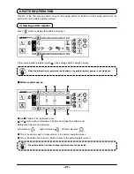
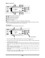
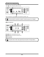
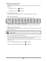
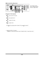
Input file No. of the media at 

2

. The file No. which has been inputted is displayed in 

­.­The­No.­is­

determined­with­

1

 after inputting the file No.

File No. input screen

Communication setting screen

6

.­Start­of­download

­ When­all­setting­procedures­have­been­completed,­press­

6

­in­the­communication­setting­screen­to­start­­

downloading.

5

.­Custom­pattern­No.­setting

­ Press­

4

­and­

5

­in­the­communication­setting­screen­to­set­the­custom­pattern­No.

2

2

1

3

6

4

5
Summary of Contents for DLU-5494N-7

Page 1: ...INSTRUCTION MANUAL CompactFlash TM is the registered trademark of SanDisk Corporation U S A ENGLISH ...

Page 2: ...NG PROCEDURE OF THE SEWING PATTERN 20 1 Selecting procedure of the sewing pattern 20 2 Editing procedure of the sewing pattern 20 3 Teaching mode 23 4 Selecting the sleeve to be sewn 23 5 Selection of the alternate sewing 24 6 Insertion and deletion of the step 25 7 Operating procedure of the number of stitches of the reverse stitching 26 8 PATTERN OPERATION 27 1 Sewing pattern register 27 2 Copy ...

Page 3: ...x following the instructions below SC 910 control box M 91 small sized motor unit separately available article 2 SET UP 1 PREFACE 1 Installing M 91 small sized motor unit 1 When tightening the screw securely insert the hexagonal wrench key into the screw hole section to tighten 2 Hexagonal wrench key is attached to M 91 3 Be careful that the motor shaft does not hit against anything If a strong sh...

Page 4: ...on Manual for the sewing machine 2 Installing to the table 1 Adjust the belt tension by turning upper and lower nuts 1 of the adjustment bolt and adjust the height of the center of the motor so that the belt sags 15 mm 9 8N when the center of the belt is pressed by hand 3 Adjusting the belt when M 91 is used Plain washer Spring washer Hexagonal nat When the belt tension is excessively low medium o...

Page 5: ...n pin Adjust the off belt prevention pin with the hexagonal wrench key supplied with the unit as accessories so that the clearance between the belt and off belt prevention pin 3 is approximately 3 mm Perform the adjustment of the cover with the hexagonal wrench key supplied with the unit as accessories At this time be careful that the screw is not excessively loosened 1 Be careful of the direction...

Page 6: ...aining amount detection sensor etc 0 CN38 CN39 Motor signal connector 1 CN32 Standing machine pedal JUKI standard PK 70 etc Sewing machine can be controlled with the external signal 2 CN34 IP 110 panel LCD panel Various kinds of programmed sewing can be executed 3 CN45 Material end detection sensor ED 4 etc 4 CN43 FAN By adding this unit optional unit B the machine can be used as 1 needle bottom a...

Page 7: ...fix KT 01 EPF p c b A asm 4 to the control box main unit using three screws 5 supplied with the unit as accessories Be careful of the inserting direction 1 Insert KT 01 EPF p c b A asm from the oblique lower section check the inserting position and insert it until click sounds since connector CN47 3 is hidden by the cover located in the upper section of the control box main unit 2 Do not forcibly ...

Page 8: ...ng the side of front cover 3 in the direction of the arrow open the front cover toward you 8 Connect 14P cord 9 coming from the machine head to connector 4 CN46 9 Connect 7P connector 7 coming from the machine head to connector 5 CN30 10 Connect connector 8 coming from the machine head to connector 6 CN38 CN39 Connect 8P connector to CN38 and in case of 9P connector connect to CN39 11 When the opt...

Page 9: ...rections When using a type with lock insert the connectors until they go to the lock The sewing machine is not actuated unless the connectors are inserted properly In addition not only the problem of error warning or the like occurs but also the sewing machine and the control box are damaged 1 The connector for connecting IP 110 is prepared When connecting insert the connector until it is locked t...

Page 10: ...he cable clip band following the attaching procedure as shown in the figure 2 When removing the cord remove the wire saddle first and the cable clip band next 3 To remove the cable clip band as show in the illustration of how to remove the cable clip band pressing the hook of cable clip band push the band to remove the cable clip band How to fix cable clip band 2 Pull How to remove cable clip band...

Page 11: ... and insert power supply cord 1 coming from the power switch into the power plug socket Route the motor output cord from the front face of the box 1 Check again the supply voltage and the voltage designated on the control box before connecting the power supply cord 2 Prepare the power switch conformed to the safety standard 3 Be sure to connect the ground wire green yellow 1 7 8 9 0 ...

Page 12: ...er the alternate stitching mode If partial shirring pattern or is selected under the alternate stitching mode LED 3 will light up If partial shirring pattern or is selected under the aforementioned mode LED 4 will light up If the machine is not operated under the alternate stitching mode both LEDs 3 and 4 will go out Note Lights up Goes out 2 Indicator lamp LED of the partial shirring process step...

Page 13: ...dial to 0 2 Turn the variable resistor VR1 1 located on the right side of the rear of the operation display panel and adjust so that the bottom feed display is set to the minimum display 3 Adjust the scale of the bottom feed pitch dial to 5 4 Turn the variable resistor VR2 2 located on the right side of the rear of the operation display panel and adjust so that the bottom feed display is set to 5 ...

Page 14: ...tions of the holes in the bracket for installing the operation panel are different from each other according to the respective models Refer to the table below No Mounted machine head Bracket type Installing hole used Part No of screw Remarks 1 DDL 9000 Type B 2 4 SS4121415SP 3 16 28 2 DLN 9010 Type B 2 4 SS4121415SP 3 16 28 3 LH 31 Type B 1 5 SS6111210SP 11 64 40 4 LZ 228 N Type B 3 4 SS4121415SP ...

Page 15: ...for type C of the operation panel through hole A in the machine table to route it to the underside of the table 2 Connect the connector of cord 1 to connector CN34 2 in the control box 3 For type C fix FG cord 3 to the power switch with wood screw 4 supplied with the panel as accessories Wire FG cord 3 after bundling it with the power cable and the like with cable clip band 5 supplied with the pan...

Page 16: ... switch 5 With without reverse feed stitch at sewing end switch 6 Reset switch This switch is used to continue sewing from the step on the way after replacing bobbin thread when bobbin thread has run out during program stitching step This is the switch to perform needle up down compensating stitching Needle up down compensating stitching and one stitch compensating stitching can be changed over wi...

Page 17: ... number of stitches has been completed This switch prohibits all thread trimmings This switch cannot be used with the sewing machine which is not provided with the automatic thread trimming device This is the switch to set the value of bobbin thread counter or No of pcs counter When moving the resistor in the left direction max speed is limited This lamp lights up when the power switch is turned O...

Page 18: ... terminal 2 Do not disassemble the operation panel to prevent it from breakage 2 Adjusting the contrast of the operation panel display 1 Press in the direction of arrow mark the click of section A of cord outlet cover 2 assembled in the rear of operation panel 1 and remove the cover 2 Connect the optional relay cable connector to CN105 3 of the production control switch connecting connector 3 Prod...

Page 19: ...ern edit screen Every time switch is pressed the screen changes Number of stitches of back tuck stitching setting screen Setting of number of stitches of reverse stitching is performed Pattern edit screen Step editing of the pattern is performed 1 Fundamental screen list Pattern operation screen Register copy or deletion of the pattern is performed ...

Page 20: ...on of the step is performed Pattern register pop up Selection of the pattern to be registered is performed Pattern copy pop up Pattern of copy source or pattern of copy destination is selected Pattern deletion pop up Pattern to be deleted is selected 2 Pop up list ...

Page 21: ...ist this screen is displayed Pattern register screen When DETERMINE key is pressed at the pattern register pop up of 2 Pop up list this screen is displayed Register and edit of the pattern is performed in this screen 3 Other screens For the details of the function refer to the Instruction Manual for IP 110 ...

Page 22: ...ern operation screen 2 Editing procedure of the sewing pattern Press switch to display the pattern edit screen 1 and 2 Number of stitches of the selected step is set Setting range 0 to 500 stitches When 0 stitch is registered to the number of stitches automatic update of the step by the number of stitches is not performed The step is manually changed over with the shirring step changeover switch l...

Page 23: ... 2 4 Confirm that step 2 is selected and set the number of stitches to 10 using switches 1 and 2 5 Set the shirring amount to 3 0 using switches 3 and 4 6 Select the next edit step using switches 5 and 6 After editing step 2 Step 1 10 stitches 2 0 mm Step 2 10 stitches 3 0 mm Step 3 20 stitches 3 5 mm Step 4 18 stitches 3 0 mm Number of stitches Shirring amount Editing procedure is shown as an exa...

Page 24: ...s 1 and 2 8 Set the shirring amount to 3 5 using switches 3 and 4 9 Select the next edit step using switches 5 and 6 After editing step 3 Step 4 10 Confirm that step 4 is selected and set the number of stitches to 18 using switches 1 and 2 11 Set the shirring amount to 3 0 using switches 3 and 4 2 1 4 3 5 6 2 1 4 3 5 6 ...

Page 25: ...e the sewing machine stop running and the number of stitches which has been sewn is displayed 5 Number of stitches can be corrected by pressing switches 3 and 4 in the state that the sewing machine has stopped 6 Proceed to the next step using switch 2 or make the sewing machine perform thread trimming This completes the input of the number of stitches of step 1 One sewing pattern has the data on l...

Page 26: ...er one Press switch to display the pattern edit screen Changeover of alternate sewing function ON OFF can be performed with alternate sewing selection switches 1 and 2 When the alternate sewing function is ON is displayed When the alternate sewing function is OFF is displayed When Without reference is selected in the data creation reference of the pattern register the sleeve selection pictograph i...

Page 27: ...e position where you desire to insert or delete with step selection switches 1 and 2 2 Press step edit switch 3 to display the step insertion deletion pop up 3 When the step insertion deletion pop up is displayed by mistake or the insertion deletion position is selected by mistake press cancel switch 4 In case of insertion 4 When step insertion switch 5 is pressed insertion of the step is executed...

Page 28: ...es 3 and 4 for setting the number of stitches A through D The range of the number of stitches that can be changed 0 to 99 stitches Operating procedure Press switch to display the number of stitches of reverse stitching setting screen Reverse stitching at the start of sewing No setting Double reverse stitching at the start of sewing No setting Double reverse stitching at the end of sewing Reverse s...

Page 29: ...reference at the time of creating the pattern is set References below can be selected Left reference Right reference Without reference 6 This is the cancel switch Screen returns to the pattern operation screen 7 This is the determination switch Screen moves to the pattern register screen Press switch to display the pattern edit screen When the information is registered to all patterns the pattern ...

Page 30: ...he teaching mode 2 The indication shown on the number of stitches input section changes to This shows that the sewing machine entered the teaching mode 3 Depress the front part of the pedal to make the sewing machine perform sewing until the last stitch of the step Caution the number of stitches is not inputted by manual turning or needle up down compensating switch 4 Return the pedal to its neutr...

Page 31: ...wing pattern copy switch 1 in the sewing pattern operation screen Pattern copy pop up When the information is registered to all patterns the pattern copy pop up is not displayed The pattern which has been already registered cannot be selected to the copy destination Press switch to display the pattern edit screen 2 Copy of the sewing pattern 2 4 6 1 3 5 1 ...

Page 32: ...ecuted Pattern deletion pop up Press sewing pattern deletion switch 1 in the sewing pattern operation screen Press switch to display the pattern edit screen When the pattern which has been registered is one the deletion pop up is not displayed 3 Deletion of the sewing pattern 2 4 1 3 1 ...

Page 33: ...ches The preset value on the bobbin thread counter is subtracted in accordance with the number of stitches detected Every time the detector detects 10 stitches 1 is subtracted from the preset value on the bobbin thread counter When the value on the counter becomes a minus value as 1 0 1 the buzzer peeps three times and the pop up display inform that the time to change the bobbin thread has come 1 ...

Page 34: ...y For the ratio display 1 0 fixed display is displayed at bottom feed amount display section 2 and the value that the top shirring amount is divided by the bottom feed amount is displayed at top shirring amount display section 3 When switch 1 is pressed the display changes to the direct display Ratio display The No of pcs counter counts up the number of finished products every time the machine per...

Page 35: ...ing is changed over This is the switch which makes the sewing machine automatically perform sewing at the specified speed until the material edge is detected when the material edge sensor is used When thread trimming prohibition switch 1 is pressed ON OFF of the thread trimming prohibition is changed over This switch is used to temporarily make the thread trimming function inoperative The other pe...

Page 36: ...itches of the step setting is performed 1 Setting is completed 2 Pattern data mirroring function is performed 1 Sewing common data 2 Sewing management information 1 Turn ON the power 2 Press switch 1 to display the information screen Setting and checking of various data can be performed with the information For the information there are the operator level and the maintenance personnel level 18 INF...

Page 37: ...nter first stitch is the ratio in terms of the difference of shirring amounts between the steps 4 Stepping motor origin position setting Origin compensation of the stepping motor which determines the shirring amount is performed Setting range is 2 5 to 2 5 mm The motor may fail to properly work Any person other than the service engineer should not operate the motor 5 Number of remaining stitches o...

Page 38: ... Mirroring processing is executed 6 Pattern data mirroring function Mirroring data inversion processing of the pattern which has been already registered is performed 7 Completion of setting Setting of the common data is completed and the screen returns to the information screen 2 Sewing management information For the details refer to Instruction Manual for IP 110 The pattern to which mirroring has...

Page 39: ...aded to the sewing pattern No 10 1 Open the media cover and insert CompactFlash TM Optional Part No 40000100 from the inserting opening Panel function does not work with the cover opened 2 Selection of data EPD is selected from the beginning since the data of EPD form only is handled for DLU 5494 3 Selection of communication method Press 2 in the communication setting screen to display the communi...

Page 40: ... to display the file No of media input screen Communication method which is selected at present is shown in reverse video Explanation of the pictograph 1 Down load from the media 2 Download from SU 1 3 Upload to the media 4 Upload to SU 1 Press 1 to select download from the media Then press 5 to determine 1 5 2 3 4 ...

Page 41: ... inputting the file No File No input screen Communication setting screen 6 Start of download When all setting procedures have been completed press 6 in the communication setting screen to start downloading 5 Custom pattern No setting Press 4 and 5 in the communication setting screen to set the custom pattern No 2 2 1 3 6 4 5 ...

Page 42: ...s 5 to determine after selecting upload to the media 4 Setting of the custom pattern No Press 4 and 5 in the communication setting screen to set the custom pattern No 5 Selection of file No of the media Press 3 in the communication setting screen to display the file No of media input screen Input the file No of the media The inputted file No is displayed in After inputting the file No determine it...

Page 43: ... delete in the file No of media input screen press switch of 3 Then the screen moves to the deletion confirmation screen 3 External interface External interface means the section to connect the operation panel and the system which is different from the operation panel For the use and details refer to the Engineer s Manual 1 Media slot Media slot is installed in the face cover located on the left s...

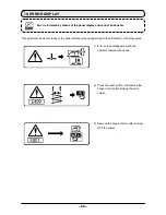
Page 44: ...ve the cause of error after erasing the error screen 3 Remove the cause of error after turning OFF the power 19 ERROR DISPLAY Error is informed by means of the panel display and control box buzzer Three different kinds of screens of the panel display screen appear due to the difference of the procedures ...

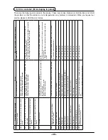
Page 45: ...hen sewing extra heavy material beyond the guarantee of the machine head When the motor does not run Motor or driver is broken Check whether the thread has been entangled in the motor pulley Check the motor output connector 4P for loose connection and disconnection Check whether there is any draw when turning motor by hand 008 Machine head connector failure Resistance pack When the machine head co...

Page 46: ...e plus 10 or more Check whether 100V 200V changeover connector is set by mistake Check whether fuse or regenerative resistance is broken In the above cases POWER circuit board has broken 813 Low voltage When voltage lower than guaranteed one is inputted When 100V is inputted for 200V setting Internal circuit is broken due to applied overvoltage Check whether the votage is lower than the rated volt...

Reviews: