JUKA ADI125 Instruction Manual Download Page 6

6

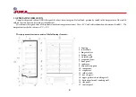
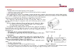
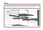
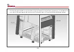
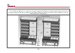
Figure 1. Adjustable supports

3. TRANSPORTATION, INSTALLATION AND COMMISSIONING

3.1. Transportation method

The unit requires careful protection against damage and accidental overturning during transportation. Glass elements and painted 

surfaces are especially vulnerable. The equipment must be in an upright (working) position both when transporting and when moving. After 

installing the equipment in a specific location, the network connection must be made after a minimum of 6 hours.

3.2. Storage method

The cabinet must always be stored in an upright position. Do not store the equipment exposed to direct sunlight or other weather 

conditions (rain, snow, etc.).

3.3. Operating site requirements

The equipment should be installed in a dry, well ventilated place that allows good air circulation (distance between the wall and the unit 

should be at least 10 cm), away from heat sources and devices that generate air flow (including fans, air conditioners).

Do not install the equipment in locations exposed to direct sunlight, rain, snow, etc.

Make sure that the cross-section of the power lines is suitable for the current power consumption.

3.4. Equipment installation and preparation for operation

Place the cabinet on the work surface and level it horizontally with the adjustable supports (Figure 1). Precise horizontal positioning 

of the equipment affects the reduction of unit noise and guarantees condensate drainage.

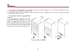
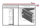
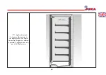
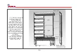
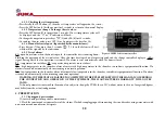
Set the brackets to the desired height and install the shelves on them.

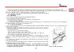
It is necessary to install the cabinet not closer than 2m from the heating devices in 

order to ensure its normal operation. Do not use the cabinet when it is exposed to direct 

sunlight, air flows from air conditioners, fans and heaters

Wash the interior and exterior surfaces of the cabinet with non-corrosive and non-

abrasiv

3.5. Connection and commissioning

Requirements for operation:

а) After transportation or storage at low temperatures, keep the cabinet at a temperature 

not lower than the operating temperature for 24 hours before start-up. Starting equipment 

that has not been warmed up can cause the compressor to jam and result in product failure

b) products intended for display in refrigeration equipment should be loaded on the shelves evenly, cooled to the temperature of the 

working volume;

c) place products in such a way that they do not interfere with the air circulation between the evaporator and the internal volume of the 

equipment;

Height adjustment

Summary of Contents for ADI125

Page 1: ......

Page 2: ...setting 19 4 1 3 Additional defrosting 19 4 1 4 Warning signals 19 4 2 Operating procedure of the Dixell electronic controller 19 4 2 1 Display 19 4 2 2 Checking the set temperature 20 4 2 3 Changing...

Page 3: ...n the equipment enclosure The equipment must be disconnected from the mains before each maintenance Work on the refrigeration system should only be performed by qualified specialists specialists train...

Page 4: ...ature from 16 to 25 C and relative humidity of no more than 60 The temperature inside the cabinet is 2 C 8 C The equipment structure consists of the following elements 1 housing 2 roller blind 3 hinge...

Page 5: ...gerated volume l 1160 1390 800 1000 1250 1550 2000 Useful volume l 930 1115 590 780 935 1170 1560 Weight of the cabinet kg 370 290 Refrigerant R404a R452a R404a R452a R290 Amount of refrigerant kg 0 9...

Page 6: ...on 3 4 Equipment installation and preparation for operation Place the cabinet on the work surface and level it horizontally with the adjustable supports Figure 1 Precise horizontal positioning of the...

Page 7: ...re The refrigeration machine works cyclically The equipment must be connected to the 230 V 50Hz mains supply for this purpose a demountable plug is provided which makes it possible to connect both thr...

Page 8: ...or if the cross sectional area of the extension cord is less than 1 5 sq mm 3 6 Operation of energy saving night blinds curtains For maintaining the temperature inside the refrigerated multideck at n...

Page 9: ...9 3 7 Assembling a line of refrigerated multideck ADX 3 7 1 Remove the front glass from the connecting windows by removing it from the groove...

Page 10: ...and brackets that hold them from the side of the multideck joint To do this lift the shelf up to the exit of the brackets holding it out of the grooves after the shelf is removed remove the brackets f...

Page 11: ...nteraction with it Hook the false wall through this hole with your finger lift it slightly until the hooks come out of the hook and pull on yourself 3 7 4 Remove the front panel take the panel from un...

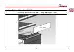
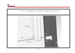
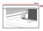
Page 12: ...12 3 7 5 Unscrew the self tapping screws and remove the rack plugs on the connection side...

Page 13: ...nstalled unscrew the bolts securing it and remove the side panel note for convenience it is recommended to place under the side panel supports made of soft material wood plastic foam etc to prevent fa...

Page 14: ...nstalled unscrew the bolts securing it and remove the side panel note for convenience it is recommended to place under the side panel supports made of soft material wood plastic foam etc to prevent fa...

Page 15: ...15 3 7 7 Apply a butyl cord d 4 mm at the junction of the display case In the case of connecting display case without a partition application to only one of the display cases...

Page 16: ...larly attach the second multideck to the panel on the opposite side note for convenience it is recommended to substitute supports made of soft material wood plastic foam etc under the blank panel to p...

Page 17: ...tion of connecting without partitions Install the air duct plug for which you need to put the cap on the flange of the upper panel while inserting the deflection of the cap between the foam insert and...

Page 18: ...er or through a jumper made of plexiglass through the upper bracket and side post with bolts M6x16 M6x25 when using a partition made of plexiglass connect the two lower mounts of the frame with M6x45...

Page 19: ...screen after 1 second the flashing temperature value will appear 2 Increase or decrease the temperature using keys 1 and 3 3 Press 2 again to confirm the new value 4 1 3 Additional defrosting The devi...

Page 20: ...rm is reset automatically when the door is closed P1 temperature sensor failure P2 evaporator temperature sensor failure HA high temperature in the chamber alarm of excessively high temperature in the...

Page 21: ...user must keep the condenser clean Contaminants make heat transfer difficult resulting in increased energy consumption as well as damage to the compressor ATTENTION THECONDENSERSHOULDBECLEANEDATLEASTO...

Page 22: ...TION AND ELIMINATION OF MALFUNCTIONS If you have any problems with the operation or start up of the equipment refer to the sections of the manual dealing with abnormal operations The purpose of this i...

Page 23: ...pacity The air vents are not blocked The evaporator is not covered with ice If necessary carry out a complete preventive defrosting of the equipment having previously moved the food to another place w...

Page 24: ...circuit This phenomenon is a technical property of the refrigeration equipment and is not a sign of malfunction If after checking the items mentioned above the equipment does not work correctly conta...

Page 25: ...g in the impossibility of further operation of the equipment flooding fire theft etc as well as under other circumstances beyond the control of the seller manufacturer when traces of any foreign objec...

Page 26: ...Warranty card Product and model Date of sale Serial number Warranty period Seller s signature Buyer s signature The buyer confirms the technical serviceability of the product...

Page 27: ......

Reviews: