OPERATING AND INSTALLATION
– MARCH 2013
WWW.JSI-UK.COM
Page 6 of 9
For the U.K. and Ireland, this appliance is suitable for connection to 230v single phase 50 Hz
supply
The connection leads are in accordance with the following codes:
Green/Yellow = Earth
Blue
= Neutral
Brown
= Live
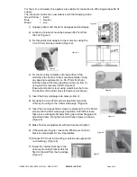
1) Unpack product and check for damages and shortages.
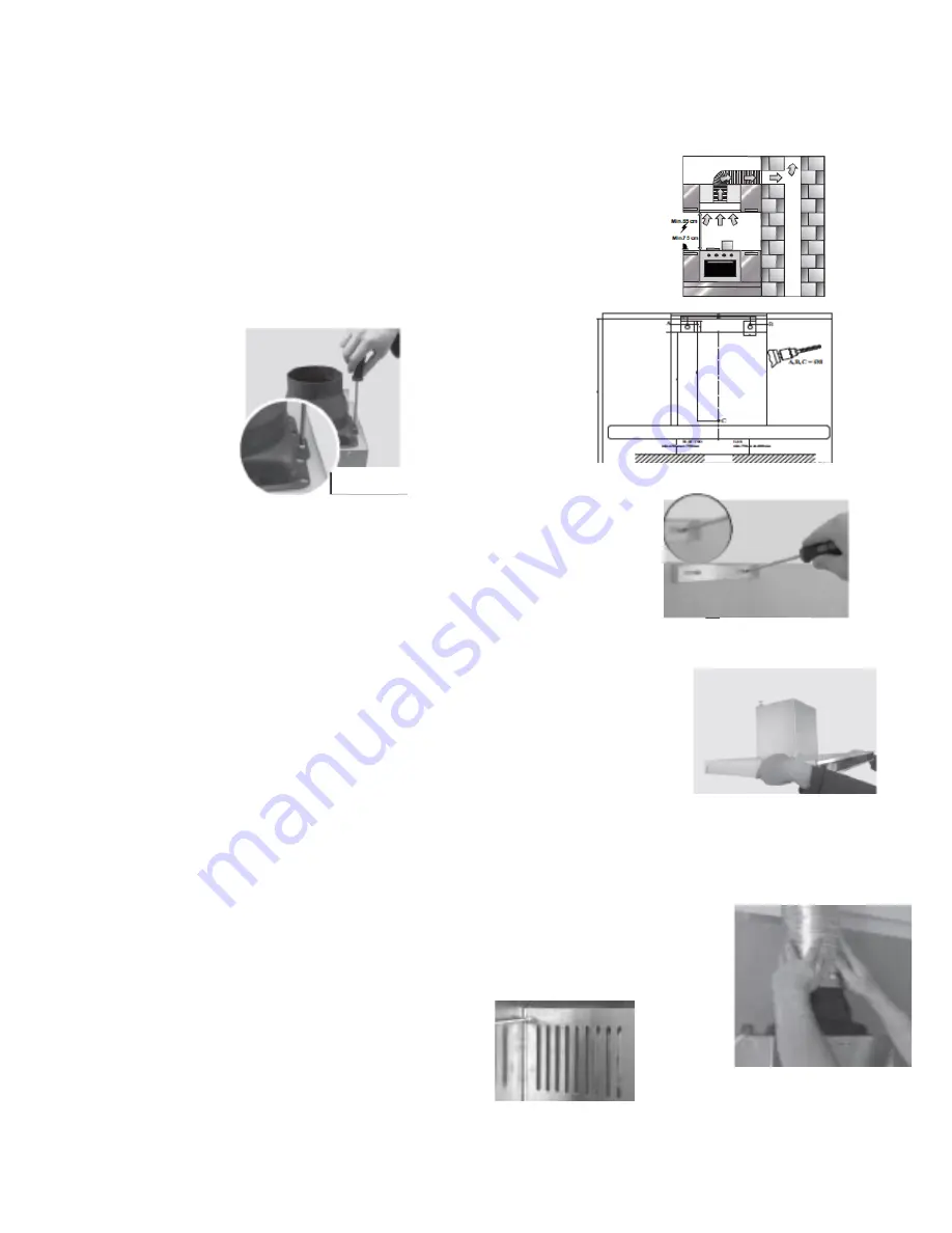
2) Location of product should be between 65-75cm from
the hob (Figure 1)
3) Fix the plastic duct adaptor to the motor box using the
3.5 x 9.5mm screws provided (Figure 2).
4) Fix the mounting template onto the surface of the
wall where the hood is to be mounted carefully noting
any spacing requirements (i.e. 65-75mm from hob).
Drill the holes at the three positions shown (A, B & C)
using an 8mm masonry drill bit. (Figure 3)
Ensure the bracket is level using a spirit level but note
The bottom of the motor block is fixed at point shown.
5) Insert the 8mm wall plugs into holes (A,B & C)
6) By using the 3.9 x 22mm screws provided, screw the
chimney mounting to the 0.6mm wall plugs. (Figure 4)
7) Insert the hood suspension screws by screwing the 5.5 x 45mm
screws into the 8mm wall plugs at position A and B but leave
these loose with approximately 5mm gap to allow hanging and
adjustment later. Hang the hood on these screws as shown.
(Figure 5)
8) Make final level adjustments with spirit level and tighten.
9) If the walls are irregular, loosen the M5 screws on motor
block to compensate for any irregularities.
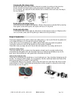
10) Connect PVC duct kit if venting to outside (as opposed to
re-circulating). (Figure 6)
11) Screw the internal chimney to the
chimney mounting bracket which is
fixed to the wall from the top edges.
(Figure 7)
Figure 1
Figure 3
Figure 7
Figure 6
Figure 4
Figure 2
Figure 5
Figure 6

