


17
General Section
Model Select / Copy
Model select allows up to 30 different models to be
stored and selected.
Note:
When setting up a new model it is recommended
that an unused model memory is selected. If a current
model memory is selected it’s recommended that the
model be reset to factory default setting before
programming the new model. See model reset on page
19.
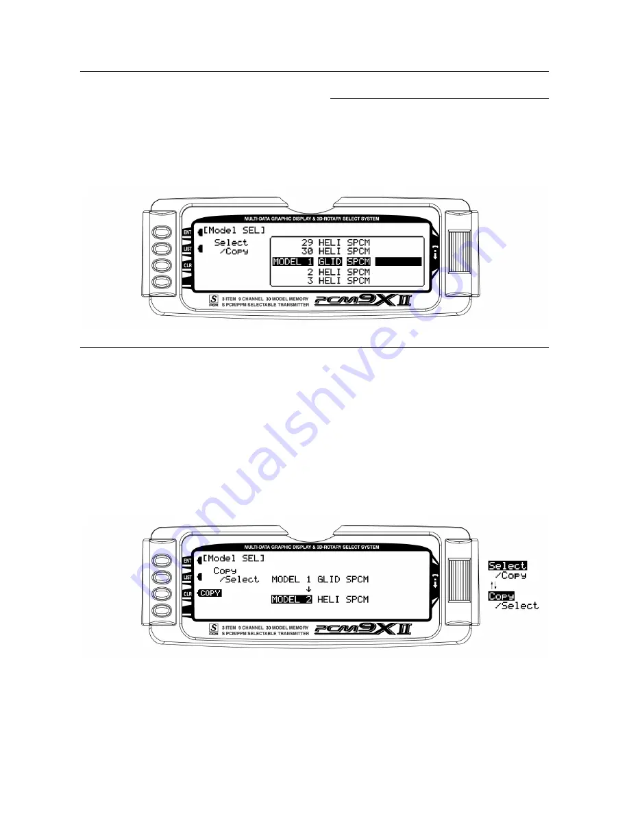
Model Select
1. In the
SYSTEM Menu
, highlight and select
Model
SEL
using the Selector.
2. Use the Selector to highlight and select the desired
model number to be used.
3. Return to the SYSTEM Menu by pressing the LIST
button.
Copy Function
1. Highlight and select
Model SEL
in the
SYSTEM
Menu
. Then highlight and select
Select
to obtain the
Copy display. The display shows the currently
selected model on top with a down-arrow pointing to
the lower model memory that the current model will
be copied into.
To change the lower model memory that is to
receive the copy of the current model
, highlight and
select the lower model name and number. Then scroll
to an unused model memory or a memory that contains
data that is no longer required, and select it.
2. Verify that the top model is the model that is to be
backed-up and the lower model is empty or contains
a model that is no longer required. When satisfied
that all is well, press the
CLR
button on the left side
of the display next to
COPY
. The entire contents of
the currently selected model is copied to the lower
model on the display and there is now a complete
backup of the current model. The upper and lower
model memory names are now the same because
the two model memories are now identical in every
regard.


