background image

SL600AC SLIDING GATE OPERATOR 


Installation of Rack   

z

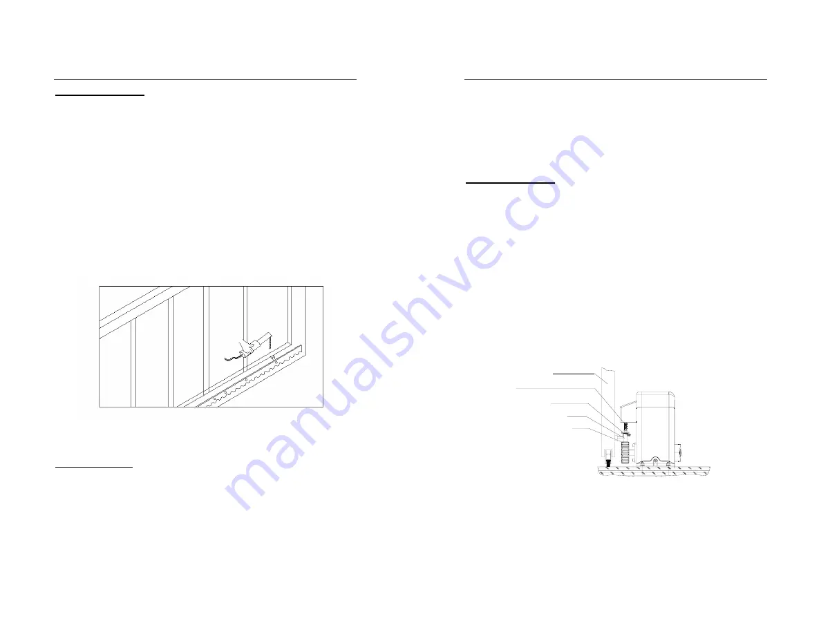
  Fix the three nuts (in the same package with rack) on the rack 

element. 

z

  Lay the first piece of rack on the gear and weld the first nut on the 

gate. 

z

  Move the gate manually, checking if the rack is resting on the 

gear, and weld the second and third nut. 

z

  Bring another rack element near to the previous one. Move the 

gate manually and weld the three nuts as the first rack, thus 
proceeding until the gate is fully covered. 

z

  When the rack has been installed, to ensure it meshes correctly 

with the gear. 

z

  The space between rack and gear is about 0.5mm.


Fig.4 

5. Adjustment   

Spring limit switch   

z

  To ensure safety, it is recommended to install limit switches at 

both ends of the gate to prevent the gate from sliding out of the 
rails. The rails must be installed horizontally. 

z

  Install the limit block as shown in Fig.5 and Fig.6. The spring limit 

switch and blocks are used to control the position of the gate. 

SL600AC SLIDING GATE OPERATOR 


7

z

  Release the gear with the key and push the sliding gate manually 

to pre-determine the position, fix the block to the rack and lock 
the gear by push up the release bar. Moving the gate electrically, 
adjust the block to the proper position until the position of the 
opening and closing meet the requirement. 


Magnetic limit switch   

z

  To ensure safety, it is recommended to install limit switches at 

both ends of the gate to prevent the gate from sliding out of the 
rails. The rails must be installed horizontally. 

z

  Install the limit block as shown in Fig.5 and Fig.6. The magnetic 

of limit switch and blocks are used to control the position of the 
gate. 

z

  Release the gear with the key and push the sliding gate manually 

to pre-determine the position, fix the block to the rack and lock 
the gear by push up the release bar. Moving the gate electrically, 
adjust the block to the proper position until the position of the 
opening and closing meet the requirement. 


Spring limit switch


Gear

Sliding gate

Rack

limit block

Spring of limit switch

Summary of Contents for SL600AC

Page 1: ...urposes 2 Important safety information Carefully read and follow all safety precautions and warning before attempting to install and use this automatic gate operator z The gate operator should be inst...

Page 2: ...0ACU Power supply 220V 50Hz 110V 60Hz Motor speed 55rpm 66rpm Rated output power of motor 180W Remote control operating distance 30m Frequency 433 92mHz Remote control mode Single button Output shaft...

Page 3: ...d should be approximately 450mm x 300mm x 200mm deep in order to providing for adequate weight and structure to insure proper stable installation Anchors see Fig 2 You can use anchor bolts anchors was...

Page 4: ...s are used to control the position of the gate SL600AC SLIDING GATE OPERATOR 7 z Release the gear with the key and push the sliding gate manually to pre determine the position fix the block to the rac...

Page 5: ...z Turn the key and pull down the release bar about 90 to release the gear Note Do not exceed 90 be careful not to use too much force otherwise the release bar will be damaged z Open and close the gate...

Page 6: ...Infrared If the infrared beam is interrupted during closing the gate will reverse and open immediately The product is not factory equipped with an infrared device the infrared output signal must be N...

Page 7: ...PE Protect Earth C and C capacitor If the door move direction is wrong please change the MOT1 and MOT2 of motor and change the block of SL600AC SLIDING GATE OPERATOR 13 limit Magnetic limit switch Mot...

Page 8: ...emote Pedestrian button After you learn the transmitter you press the remote button 4 the door will open 1 meter when the door is closed z You can program learn button 1 button 2 and button 3 individu...

Page 9: ...When the 3 OFF and the 4 is ON auto close time is near 12 Sec when the 3 ON and the 4 is OFF auto close time is near 24 sec when the 3 and the 4 is all in ON position the auto close time is near 36 s...

Page 10: ...120 C and switch on the motor automatically when the temperature is lower than 85 C 5 C 9 LED indicate a LED of Power indicated the input power b LED of LEARN indicated the transmitter learn status c...

Page 11: ...mote transmitter does not work 1 Battery level may be low 2 Transmitter code is lost 1 Replace the battery inside the transmitter 2 Reprogram the transmitter The transmitter operating distance is too...

Reviews: