Jøtul GF 400 BV Sebago Installation And Operation Instructions Manual Download Page 14

14

138301_Rev_G   10.4.11

Gas Pressure

Correct gas pressure is essential for efficient and safe 

operation of the GF 400 BV gas stove.  It is important 

that the correct pressure is established at the time of 

the installation.  Proper gas pressure provides a consis-

tent flow of gas to the appliance and is instrumental in 

checking for gas leaks.

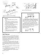
Pressure Test:  Attach a manometer to the appro-

priate test point on the valve. See fig. 19. The gauge 

connections are located on the front of the valve under 

the On/Off/Pilot- knob.  Gauge connections are identi

-

fied by:

E -    for Inlet or Supply Pressure (the amount of gas 

coming to the valve.)

A -   for Manifold Pressure (the amount of gas that 

is coming out of the valve to the burner.) 

ALWAYS TEST PRESSURES WITH VALVE CONTROL 

KNOB SET ON HIGH.

INLET GAS PRESSURES 

(inches water column)


MIN


MAX


NATURAL GAS   5.0 

7.0 


PROPANE 

12.0 

14.9

The appliance and its appliance main gas valve 

must be disconnected from the gas supply piping 

system during any pressure testing on that system 

at test pressures in excess of 1/2 psig (3.5 kPa).

The appliance must be isolated from the gas 

supply line by closing its individual manual gas 

shut-off valve (gas cock) during any pressure testing 

of the gas supply piping system that is equal to or 

less than pressures of 1/2 psig (3.5 kPa).

MANIFOLD PRESSURES

(inches water column)


MIN


MAX


NATURAL GAS  1.2 

3.8 


PROPANE 

2.9 

11.0

Figure 19.   Pressure test points.

Leak test:

1.  Mix a 50-50 solution of water and dish 

soap.

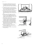
2.  Light appliance- see lighting instructions 

on the inside back cover of this manual or 

on the stove’s rating plate.

3.  Brush or spray all joints and connections 

with the soapy water solution.

4.  If bubbles appear at any connection or 

seam or a gas odor is detected, imme-

diately turn gas control knob to the OFF 

position.

5.  Tighten or reconnect the leaking joint 

and retest for any gas leaks.

Figure 18.  Supply valve connection fittings.

E

A








Summary of Contents for GF 400 BV Sebago

Page 1: ...r future reference QUEFAIRESIVOUSSENTEZUNEODEURDEGAZ Ne pas tenter d allumer l appareil Ne touchez aucum interrupteur Ne pas vous servir des t l phones se trouvant dans le b timent o vous trouvez Appe...

Page 2: ...d air intake must be used Installation shall be in strict compliance with the manufacturer s instructions A copy of the installation instructions must remain with the appliance or equipment at the com...

Page 3: ...space below You may also wish to attach your purchase receipt to this page for future reference MODEL NAME J tul GF 400 BV Gas Stove SERIAL NUMBER _______________________________ DATE OF PURCHASE ____...

Page 4: ...E APPLIANCE IS INSTALLED SEE PG 11 With Short Legs reduce height by 2 1 4 51 mm 13 330 mm Rear Exit 23 1 2 597 mm C L 6 3 4 171 mm 24 609 mm 28 711 mm 26 3 4 679 mm 13 330 mm 4 1 2 114 mm 13 1 4 336 m...

Page 5: ...ing if a proposed installation is acceptable Any requirement that is requested by the local authority having jurisdiction that is not specifically addressed in this manual defaults to local code In th...

Page 6: ...doivent tre avertis des dangers des temp ratures de surface lev es et devraient rester l cart pour viter les br lures ou l inflammation des v tements Young children should be supervised while they ar...

Page 7: ...Maintain clearances to combustibles as noted above Width 32 81 cm Depth 24 61 cm Height 61 155 cm Approved Wall Pass Through Use only 4 Simpson Dura Vent Wall Thimble 3143 to pass the vent pipe throu...

Page 8: ...e B cap is required See diagrams page 10 Venting on the Sebago CANNOT be less than 4 in diameter or greater than 4 in diameter Any unused flue or masonry enclosure can be used as a passage way for ven...

Page 9: ...NENT When installing at an altitude above 2000 the mini mum vertical rise becomes 12 from the draft hood Figure 6 Venting through a masonry chimney Listed termi nation cap required Storm collar requir...

Page 10: ...90 Elbows Minimum chimney height from Draft Hood is 7 feet Minimum chimney height from Draft Hood is 7 feet Maximum chimney height off Draft Hood is 35 feet Minimum chimney height off Draft Hood is 7...

Page 11: ...IAN IN ACCORDANCE WITH THE MANUFACTURER S INSTRUCTION AND ALL CODES AND REQUIRE MENTS OF THE AUTHORITY HAVING JURISDIC TION FAILURE TO FOLLOW THESE INSTRUC TIONS COULD RESULT IN SERIOUS INJURY OR PROP...

Page 12: ...two support brackets at the front of the firebox and push the plate back toward the rear of the firebox 11 CHANGE THE PILOT ORIFICE From within the firebox remove the Pilot Head by pulling it straight...

Page 13: ...rews securely 16 Install the identification labels to the stove so that they can be seen by any person that may be servicing the stove Label A apply to back of stove Label B apply to stove s rating pl...

Page 14: ...2 0 14 9 The appliance and its appliance main gas valve must be disconnected from the gas supply piping system during any pressure testing on that system at test pressures in excess of 1 2 psig 3 5 kP...

Page 15: ...T THE PILOT ASSEMBLY OPENING Do not pile the embers against the burner skirt edges See fig 24 Figure 20 Engage the holes in the underside ot the Right Log with the peg in the burner skirt Figure 22 In...

Page 16: ...PLIANCE Figure 26 Valve and Accessory wiring diagram Flame Appearance Air Shutter Adjustment This stove is shipped from the factory equipped to burn Natural gas If the stove has been converted for use...

Page 17: ...ob located in the center of the valve face Fire intensity can be adjusted up to 50 between the LOW and HIGH settings See fig 29 NO SMOKE OR SOOT SHOULD BE PRESENT CHECK LOG PLACEMENT IF ANY SOOT OR SM...

Page 18: ...he stove is cold and there are NO hot embers 5 Remember this appliance has a continuous burning pilot flame Exercise caution when using products having combustible vapors Always shut off gas supply wh...

Page 19: ...ealed according to the manufac turer s instructions provided at the initial installation Burner and Logset Periodically inspect the Firebox Valve Compartment Convection Airways and optional Blower to...

Page 20: ...6 flange head hex bolts as shown in fig 34 4 Attach the Duct Deflectors using the two 7 x 1 2 screws together with the finger guard mounting screws already in place See 7 and 11 in fig 33 5 Install th...

Page 21: ...ically when the stove cools down If automatic blower circulation is not desired place the blower control switch in the MANUAL position Figure 37 Blower Wiring Diagram Figure 36 Blower Controls CAUTION...

Page 22: ...eir own against the wall Push them back against the Rear Panel 6 Reinstall the Logset See page 21 BE CERTAIN THAT NO EMBERS ARE BLOCKING THE PILOT ASSEMBLY OPENING 7 Replace the Glass Frame Slide the...

Page 23: ...APPAREIL CONVERTI EST CHEQUE SUIVANT LES CRITERES ETABLIS DANS LES INSTRUCTIONS DE PROPRIETAIRE PROVISIONNEES AVEC L EQUIPEMENT Derating Procedure 1 Follow Steps 1 10 of the Fuel Conversion procedure...

Page 24: ...24 138301_Rev_G 10 4 11 ONLY USE REPLACEMENT PARTS PROVIDED BY AN AUTHORIZED J TUL DEALER Figure 44 J tul GF 400 BV Sebago Illustrated Parts Breakdown...

Page 25: ...on Kit to Natural Gas 156006 High Altitude Adjustment Kit LP 155885 High Altitude Adjustment Kit NG 155895 45 Gasket Pilot Asy 129670 48 Control Door 2211892 49 Spacer 118040 50 Fender Washer 1 50 dia...

Page 26: ...osts associated with the repair of gas controls plumbing burners log set or sheet metal firebox beyond the warranty period 5 Damage caused by unauthorized modification use or repair 6 Damage to enamel...

Page 27: ...knob Never use tools If the knob will not push in or turn by hand do not try to repair it Call a qualified technician Force or attempted repair may result in a fire or explosion D Do not use this appl...

Page 28: ...beginning the installation it is important that these instructions be carefully read and understood J tul maintains a policy of continual product development Consequently products may differ in speci...

Reviews: