background image

10

Fig. 10

A

B

3.  Fasten the cover 

(A)

 with the screws 

(B)

.

Fig. 11

A

4.  Cut out the part 

(A)

 in the heat shield for the 

fl

 ue pipe.

Fig. 12

5.  Install the rear heat shield onto the stove.

Fig. 13

1

2

6.  Remove the protective paper from the gasket and fasten it 

around the outside of the 

fl

 ue pipe.

ENGLISH

Summary of Contents for F 100 ECO.2 LL

Page 1: ...ie en montagehandleiding 61 DE Montage und Gebrauchsanleitung 75 J tul F 100 ECO 2 Manual Version P03 Manualen m oppbevares under hele produktets levetid Manualen skal opbevares under hele produktets...

Page 2: ...gy efficiency index 1 Efficiency at nominal heat output 8 Any specific precautions that shall be taken when the local space heater is assembled installed or maintained Fire safety precautions such as...

Page 3: ...nerse en cuenta durante el montaje instalaci n o mantenimiento del equipo de calefacci n x Precauzioni specifiche da prendere quando il riscaldatore viene assemblato installato o mantenuto in uno spaz...

Page 4: ...ent combustion in this context means normal use of the fireplace i e fuel is added as soon as the fuel has burnt down to a suitable amount of embers Register your fireplace at jotul com for a 25 year...

Page 5: ...2 SL SE J tul F 100 ECO 2 LL and J tul F 100 ECO 2 LL SE must be fitted with a permanent stop to prevent closure of the secondary air control beyond 40 open 3 1 Fire Prevention Measures There is a cer...

Page 6: ...nal hearth which must have an extension of minimum 350 mm in front of the stove For further information please see Approved Document J2010 Section 2 22 J tul F 100 ECO 2 LL Long Legs J tul F 100 ECO 2...

Page 7: ...ineral wool cilicate plates etc materials that do not burn Note A short distance to non combustible wall may lead to desiccation and discoloration of paint and cause cracking The stove must be set up...

Page 8: ...han 470 mm2 A 1 Push the air vent A to the right B 2 Use the pin screw B from the bag of screws and screw it onto the burnchamber 4 2 Installation Assembly of flue pipe with top outlet The product is...

Page 9: ...be rear mounted do the following NB In order to make the change you must first remove the ba e plate see fig 23 24 Remember to put it in place later Fig 7 A 1 Unscrew the screw A and remove the rear...

Page 10: ...screws B Fig 11 A 4 Cut out the part A in the heat shield for the flue pipe Fig 12 5 Install the rear heat shield onto the stove Fig 13 1 2 6 Remove the protective paper from the gasket and fasten it...

Page 11: ...fireplace Use 2 0 Technical Data to calculate the correct chimney cross section The chimney must be connected in accordance with the installation instructions of the chimney supplier Before a hole is...

Page 12: ...must not be operated with air controls appliance dampers or door left open except as directed in the instructions Operation with the door open can cause excess smoke The appliance must not be operated...

Page 13: ...firebed to light a new fuel charge excessive smoke emission can occur Refuelling must be carried out onto a su cient quantity of glowing embers and ash that the new fuel charge will ignite in a reaso...

Page 14: ...mover In order to prevent a water and tar layer from forming in the fireplace you should regularly allow the fire to burn hot in order to remove the layer An annual internal cleaning is necessary to g...

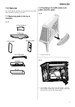
Page 15: ...haust deflector Baffle plate Left burn plate Right burn plate Rear bottom plate Fire grate Ash pan 7 2 Replacing the ba e plate burn plates and fire grate Fig 22 1 Remove the ash lip Fig 23 1 2 2 Lift...

Page 16: ...ft the fire grate and tilt it out Fig 27 A Remove the rear bottom plate A When refitting First place the rear bottom plate Place the ash pan and the fire grate Place the left side burn plate Put the b...

Page 17: ...ard be kept together with the receipt J tul AS also guarantees that steel plate parts are free from defects in materials or manufacturing at the time of purchase for a period of 5 years from the date...

Reviews: