background image

6

Servicing and testing

6.3

Test instructions

Depending on the conditions of use, but no later than every 50,000

km or every six months, the fifth wheel coupling, the mounting plate,

the slider and the king pins should be checked for:

Function

Wear

Correct position of the fastening elements (check prescribed

torque values)

Damage or distortion

Cracks

Corrosion

To ensure adequate lubrication

To ensure the smooth running of the mechanisms

and repaired where necessary (see the appropriate JOST repair in-

structions at www.jost-world.com).

6.4

Wear test

Fifth wheel couplings and king pins are subject to more or less wear

depending on the conditions in which they are used, and this wear

is noticeable by play towards the front of the vehicle. Excessive play

causes shocks and may lead to instability on the road and damage to

the fifth wheel coupling, mounting plate, sliders and vehicle chassis.
JOST fifth wheel couplings have a manual infinite adjustment facility

for the locking mechanism to extend their service lives.

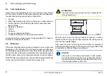
ATTENTION!

The wear on the king pin must not be compensated for

through adjustment.

71

-73 mm

84-82.5 mm

49

-50.8 mm

JSK40/05

When the wear limit on the king pin has been reached, it must be

replaced. After the king pin has been replaced, the locking mecha-

nism must be adjusted again.
Play caused by wear on the king pin should either be accepted if

within the permitted wear limit for the king pin (see Figure JSK 40/05)

or should be rectified by fitting a new king pin.

ADVICE!

After  work  on  the  locking  mechanism  or  after  replace-

ment of the lock jaw, wearing ring or locking bar, the lock-

ing mechanism must always be readjusted in order to en-

sure the base clearance of 0.3 mm.

20

MUB 002 004 M01

 (REV-C)  

04-2019

JSK 36 & JSK 37

JOST IND (REV-A) 06-2019

JSK 39

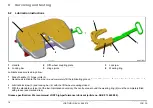
 & tear(wearing ring, lock jaw, locking bar & rubber bush,etc.)

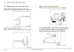
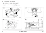
6.4.1   Wearing ring, lock jaw, rubber bush check

Check the wear state of the wearing out of limit size.
Note: It must be replaced when the limit size is exceeded.

JSK38/59

Check the wear state of the lock jaw.

Note:  It must be replaced when the limit size is exceeded.

JSK38/33

Check the wear state of the rubber bush.
Note: It must be replaced when the limit size is exceeded.

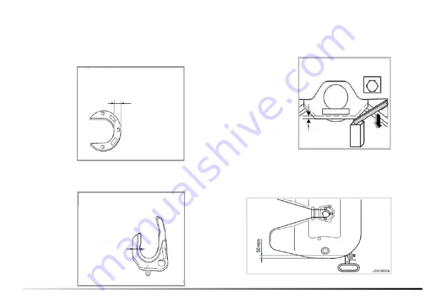
≤5mm

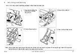
The material thickness on the top plate of the coupling plate is
10mm.The FWC must be replaced if the material thickness at
any point is less than 5mm. On the out side, however
(50mm wide) a minimum thickness of 3mm is permitted.

21

21

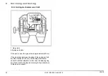
JSK 39

2" - 55.1-53.1 mm

2"  -57.5-56.0 mm

Summary of Contents for JSK 39

Page 1: ...JSK 36 JSK 37 EN Installation and operating instructions JSK 36 JSK 37 EN Installation and operating instructions 9 39 ...

Page 2: ...aterial and tightening torques 14 6 Servicing and testing 15 6 1 Servicing instructions 15 6 1 1 Fifth wheel coupling with manual lubrication 15 6 1 2 Fifth wheel coupling with central lubrication connection version Z 16 6 1 3 Low maintenance fifth wheel coupling with top plate liners version W 16 6 1 4 Grease specification 17 6 2 Lubrication instructions 18 6 3 Test instructions 20 6 4 Wear test ...

Page 3: ...n occur if the relevant safety instruc tions are not followed ATTENTION Means that slight physical injury or material damage can occur if the relevant safety instructions are not followed ADVICE Contains additional important information EN JSK 36 JSK 37 MUB 002 004 M01 REV C 04 2019 3 JOST IND REV A 06 2019 ...

Page 4: ...heel coupling and skid plate on the se mi trailer if they are in perfect technical condition The front edge of the skid plate must not be sharp otherwise it may damage the fifth wheel coupling or the top plate liners Comply with the relevant safety regulations when connecting a semi trailer for example the Health and Safety at Work Regu lations Only couple up a semi trailer on firm flat ground Whe...

Page 5: ...st be provided between the fifth wheel coupling and the vehicle chassis in vehicles that are used for transporting hazardous substances In general bolt connections are to be tightened to the tightening torque specified as a setpoint for torque wrenches as per DIN ISO 6789 in classes A or B The fifth wheel coupling must be installed on the vehicle in accor dance with the requirements of Annex 7 of ...

Page 6: ... modifications reserved The latest information can be found at www jost world com 3 2 Unintended use The following will be deemed to be unintended use Use of king pins which do not comply with the ISO 337 or DIN 74080 standards Use of defective king pins Defects may include for example damage to the king pin incorrect dimensions and installation on uneven or damaged skid plates Use with plastic di...

Page 7: ...ight of the semi trailer t T Permissible gross weight of the tractor unit including U t U Maximum imposed load t D g x kN 0 6 x T x R T R U Sample calculation R 33 t T 17 t U 10 5 t D 9 81 x 83 6 kN 0 6 x 17 x 33 17 33 10 5 Please see the adjacent table for the permitted load data for JOST fifth wheel couplings This information is also listed in the relevant JOST catalogue sheets and stamped on th...

Page 8: ... kN 3 Maximum imposed load U in t 4 Article no 5 Factory number 6 Type Permissible load data ECE Test symbol and approval number Type Fifth wheel coupling Im posed load U t D value kN E1 55R 01 0116 JSK37C JSK37C JSK37CW 20 152 JSK37E JSK37EW JSK37ER JSK37ERW 20 152 JSK37EA JSK37EAW 18 135 E1 55R 01 0294 JSK37E JSK37ME140 JSK37ME140W 15 126 E1 55R 01 1929 JSK37CX JSK37CX 24 170 E1 55R 01 1927 JSK3...

Page 9: ...3 Lock jaw 4 King pin 5 Safety catch 4 2 Fifth wheel coupling ready for engagement G50 18 1 2 3 4 5 1 Handle 2 Locking bar 3 Lock jaw 4 King pin 5 Safety catch EN JSK 36 JSK 37 MUB 002 004 M01 REV B 12 2018 9 1 2 3 4 latch latch JSK 39 JOST IND REV A 06 2019 1 2 3 4 JOST IND REV A 06 2019 JSK 39 ...

Page 10: ...ures G50 20 G50 21 and G50 22 4 4 Coupling up a semi trailer Secure the semi trailer to prevent it rolling away The fifth wheel coupling must be ready to engage see section 4 2 If it is not open the fifth wheel coupling see section 4 3 Check the height of the semi trailer The skid plate must ideal ly be at the same height as or no more than 50 mm lower than the fifth wheel coupling plate Drive the...

Page 11: ...under the semi trailer The fifth wheel coupling is automatically ready for engagement again see section 4 2 4 6 Checking the locking mechanism G50 23 1 The catch 1 must be down as shown JSK40 15 ATTENTION The skid plate must rest on the fifth wheel coupling without a gap G50 31 ADVICE To prevent the fifth wheel coupling being opened without authorisation a se curity device for example a padlock ca...

Page 12: ...st plates with zero play Use the welding methods set out by the manufacturers of the vehicle and mounting plate for this purpose see section 5 2 There is no need to use thrust plates however if it can be ensured that the correct tightening torque for the bolts and therefore the per fect friction contact can be generated and maintained at all times The bolt connections are therefore to be designed ...

Page 13: ...onal bolt DIN EN 28765 28676 DIN 960 961 M16 x 1 5 8 8 8 Washer 17 DIN7349 6 thick min HV295 9 Optional washer min HV295 or disc spring 10 Hexagonal nut DIN980 M16 x 1 5 8 8 or M20 x 1 5 8 8 11 Hexagonal bolt DIN EN 28765 28676 DIN 960 961 M16 x 1 5 8 8 or M20 x 1 5 8 8 12 Optional washer disc spring ADVICE Tightening torques must absolutely be adhered to see section 5 3 EN JSK 36 JSK 37 MUB 002 0...

Page 14: ...EN 28765 28676 DIN 960 961 fine thread M16 x 1 5 M20 x 1 5 Hexagonal bolt DIN 7991 M16 or M16 x 1 5 M20 or M20 x 1 5 210 Nm 410 Nm 225 Nm 460 Nm 170 Nm 330 Nm 260 Nm 500 Nm 280 Nm 500 Nm 250 Nm 400 Nm ADVICE The values shown above are guide values for a coefficient of friction µ tot 0 14 Further information is available in VDI 2230 14 MUB 002 004 M01 REV C 04 2019 JSK 36 JSK 37 JOST IND REV A 06 2...

Page 15: ... be checked The unevenness of the skid plate must be no more than 2 mm in the load bearing section of the fifth wheel coupling The skid plate must cover the fifth wheel coupling s set down surface in every position 6 1 1 Fifth wheel coupling with manual lubrication At short intervals at the latest every 5 000 km Uncouple the semi trailer Clean the fifth wheel coupling and the skid plate Grease the...

Page 16: ...x months in harsh condi tions every 25 000 km Uncouple the semi trailer Clean the skid plate and the king pin Lightly grease the king pin and the locking mechanism parts with high pressure grease EP JOST high performance lubri cant article no SKE 013 440 000 Check the top plate liners for signs of wear and damage see section 6 6 ADVICE The pivot bearings on the C and E versions require no servicin...

Page 17: ...an the fifth wheel coupling you may pro duce waste products that contain polluting substances We would like to point out that you must comply with the various national waste regulations for the disposal of this waste 6 1 4 Grease specification We recommend high pressure grease EP e g JOST high perfor mance lubricant article no SKE 013 440 000 EN JSK 36 JSK 37 MUB 002 004 M01 REV C 04 2019 17 JOST ...

Page 18: ...sion the top plate liners do not have to be greased JOST top plate liners are resistant to lubricating greases Lubricate lock jaw 3 and locking bar 4 with the fifth wheel coupling closed With the standard version not the low maintenance version the centre area around the wearing ring 6 must be completely filled with grease see marked area Grease specification We recommend JOST high performance lub...

Page 19: ... pull handle 2 until the lock jaw 1 is free Hold handle 2 in this posi tion 3 1 G50 041 Swivel lock jaw 1 forward e g with a large slotted screwdriver until the locking bar 3 is free 3 2 1 G50 042 Slowly move handle 2 into closed position Grease all sides of lock jaw 1 and locking bar 3 ATTENTION Open the fifth wheel coupling before it is next coupled up see section 4 3 EN JSK 36 JSK 37 MUB 002 00...

Page 20: ...d damage to the fifth wheel coupling mounting plate sliders and vehicle chassis JOST fifth wheel couplings have a manual infinite adjustment facility for the locking mechanism to extend their service lives ATTENTION The wear on the king pin must not be compensated for through adjustment 71 73 mm 84 82 5 mm 49 50 8 mm JSK40 05 When the wear limit on the king pin has been reached it must be replaced...

Page 21: ...JSK40 05 When the wear limit on the king pin has been reached it must be replaced After the king pin has been replaced the locking mecha nism must be adjusted again Play caused by wear on the king pin should either be accepted if within the permitted wear limit for the king pin see Figure JSK 40 05 or should be rectified by fitting a new king pin ADVICE After work on the locking mechanism or after...

Page 22: ...cle chassis JOST fifth wheel couplings have a manual infinite adjustment facility for the locking mechanism to extend their service lives ATTENTION The wear on the king pin must not be compensated for through adjustment 71 73 mm 84 82 5 mm 49 50 8 mm JSK40 05 When the wear limit on the king pin has been reached it must be replaced After the king pin has been replaced the locking mecha nism must be...

Page 23: ...ompensated for through adjustment 71 73 mm 84 82 5 mm 49 50 8 mm JSK40 05 When the wear limit on the king pin has been reached it must be replaced After the king pin has been replaced the locking mecha nism must be adjusted again Play caused by wear on the king pin should either be accepted if within the permitted wear limit for the king pin see Figure JSK 40 05 or should be rectified by fitting a...

Page 24: ...s been replaced the locking mecha nism must be adjusted again Play caused by wear on the king pin should either be accepted if within the permitted wear limit for the king pin see Figure JSK 40 05 or should be rectified by fitting a new king pin ADVICE After work on the locking mechanism or after replace ment of the lock jaw wearing ring or locking bar the lock ing mechanism must always be readjus...

Page 25: ... locking bar into its limit position Release the handle 1 lift the safety latch see figure G50 20 in section 4 3 swing into position B and hold get someone to assist Tighten the adjusting screw 3 again until the handle 1 starts to move have an assistant check this To set the recommended basic play of 0 3 mm tighten the ad justing screw 3 by a further 1 turns and secure it with the lock nut 4 Apply...

Page 26: ......

Page 27: ...y Tel 49 6102 295 0 tkd technik jost world com www jost world com MUB 002 004 M01 REV C 04 2019 4 0 1000178 JOST IND REV A 06 2019 India 91 0 657 6617500 sales coordinator jost world com www jost world com 832108 ...

Reviews: