background image

16

 –English

INSTALLATION

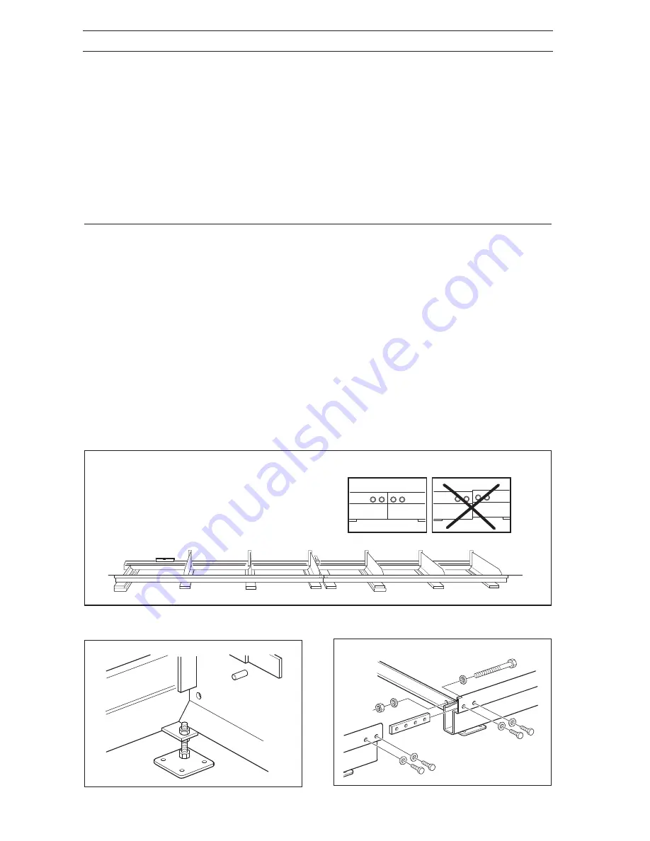
Bolted joint

Adjustable foot

Aligning the rails

Installation Site

The one-man sawmill with petrol engine should be
installed outdoors.
There should be space to lay out timber and sawn
wood.

Rails

Place the rail sections after each other on the
transverse wooden beams, which are placed under
each log bolster, and an extra transverse wooden
beam by the joints between the sections.

Installation

Unpack the one-man sawmill and check that the
delivery is complete. Check that no parts are
damaged. If any part is damaged, report this to the
carriers.
The operator’s manual includes detailed instructions
about safety, assembly, use, and maintenance of the
one-man sawmill.

Unpacking

1.

Rail sections (quantity according to the order)

2.

Saw carriage

3.

Feed unit

4.

4 rail guards

5.

Bar and chain

6.

Assembly components

Parts that are included are pictured in the Description
section on page 7-9 . Component parts are packed
according to the following:

Continue as follows:
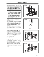
1. Assemble the adjustable feet under each of the 16

log bolsters. Adjust, by using the adjustable feet and
the rails’ bedding, until the rail sections form a
straight line and the rails sit firmly on each wooden
beam. See FIG. 21.

2. Loosely bolt together the rail sections using the

supplied jointing plates and M12 nuts and bolts. See
FIG. 23.

3. Finely adjust the rails and tighten all the bolts.

Tighten the bolted joints to 5-10 Nm. See FIG. 21.

4. Fit the stops to the ends of the rails (see page 14,

FIG. 11), as well as the folding stops, log lift, and log
lock (see page 13, FIG. 10).

5. Load the rails above each wooden beam and check

that the rails do not move.

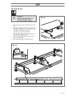
FIG. 21

FIG. 22

FIG. 23

Summary of Contents for SM 2055 E

Page 1: ...Operator s Manual Please read these instructions carefully and make sure you understand them before using the one man sawmill SM 2186 SM 2055 E ...

Page 2: ...2 English TABLE OF CONTENTS Introduction 3 Symbols 4 Warning Signs 4 Safety Regulations 5 Description 7 Installation 16 Fuel Handling 21 Starting and Stopping 23 Use 25 Maintenance 29 Technical Data 33 ...

Page 3: ...dures that can be performed by the operator More comprehensive servicing or troubleshooting should be performed by the dealer s service personnel The operator s manual describes all the requisite safety features and should be read and understood by the user before the sawmill is assembled Symbols and warning signs shown on the next page can be found in this operator s manual and on the one man saw...

Page 4: ...on should be used Read this manual carefully and make sure you understand it before attempting to use the one man sawmill Exercise caution Protective gloves should be worn Eye protection and hearing protection should be used Boots or work shoes with steel toecaps and non slip soles should be worn Eye protection should be used Protective gloves should be worn Switch off the engine by moving the sto...

Page 5: ...t of this manual Safety Regulations WARNING Always ensure good ventilation Exhaust fumes and sawdust can cause injury or allergies Personal Protective Equipment The person or persons using the one man sawmill or remaining in its close proximity must be equipped with the personal equipment as set out below 1 Hearing protection 2 Eye protection 3 Approved protective gloves 4 Boots or work shoes with...

Page 6: ...gn objects and the ground within the risk zone should be flat so that the operator avoids stumbling Personnel The following apply to personnel using the one man sawmill 1 Shall have read and understood the content of this operator s manual 2 Must not be under the influence of alcohol or medication nor suffering from tiredness 3 Good lighting is required when using the sawmill outside daylight hour...

Page 7: ...id rail 11 Idler adjustment screw for saw height 12 Height setting lock DESCRIPTION 13 Underlying support wheel 14 Scale pointer with scale 15 Indicator 16 Handlebars 17 Throttle 18 Throttle lock 19 Throttle cable 20 Support foot 21 Scraper 22 Rail stop 23 Machine plate 24 Bar and chain Tools and operator s manual A Open ended spanner 13 15 mm B Open ended spanner 17 19 mm C Socket spanner D Combi...

Page 8: ... setting lock 13 Underlying support wheel 14 Scale pointer with scale 15 Indicator Tools and operator s manual A Open ended spanner 13 15 mm B Open ended spanner 17 19 mm C Socket spanner D Combination spanner 13 19 E Combination spanner F Allen key 6 mm G Allen key 4 mm H This operator s manual 16 Handlebars 20 Support foot 21 Scraper 22 Rail stop 23 Machine plate 24 Bar and chain 25 Oil tank 26 ...

Page 9: ...er supports short and long 4 Log bolster 5 Log lock 6 Adjustment nut 7 Saw carriage 8 Protective loop 10 Skid rail 11 Idler adjustment screw for saw height 12 Height setting lock 13 Underlying support wheel 14 Scale pointer with scale 15 Indicator 16 Handlebars 20 Support foot 21 Scraper 22 Rail stop 23 Machine plate 25 Oil tank 26 Motor console 27 Connector with phase inverter 28 Electric motor 2...

Page 10: ... 14 There are two red markings on the scale that indicate the lowest saw height with the timber support raised one red line for the long timber support and one red line for the short one CAUTION Sawing under the respective markings will damage the chain and there will be a risk of sparking Frame FIG 3 and FIG 4 The carriage frame consists of welded square tubing with requisite corner reinforcement...

Page 11: ... saw FIG 7 The chain saw is secured in a vibration free plate 9 that is screwed into the saddle The vibration free plate is supplied with an adjustment option where the position of the saw in relation to the rails can be adjusted The saddle is installed in the saw carriage and is adjusted vertically with an idler adjustment screw Bar and chain FIG 7 The bar and chain A are installed on the engine ...

Page 12: ... in a special mounting that is screwed onto the saw For a further description of the chain saw see the enclosed operator s manual for the chain saw FIG 9 FIG 10 FIG 11 9 18 17 24 35 Electric motor feed unit FIG 11 The feed unit is powered by a 42 volt DC motor 35 The speed of the motor is controlled variably from the control box Electric Motor FIG 10 The one man saw is powered by a 3 phase motor 2...

Page 13: ...the log so that the core becomes horizontal Rails The rails consist of two sections standard delivery Each section is 3 m The sections are aligned and bolted together into a track for the carriage The rail sections are bolted together and fastened using M12 bolts with nuts which assures stability and ensures that the carriage runs straight The rails also have a number of transverse log bol sters d...

Page 14: ...saw carriage is equipped with four rail guards that run above the rails The rail guards have the tasks of keeping the rails clean and preventing crush injuries between the runner wheels and rails Adjustable Support Feet Adjustable support feet are mounted by each log bolster You can fine tune the rails adjustment using the support feet FIG 16 FIG 15 FIG 14 ...

Page 15: ...h a centrifugal clutch on both the sawmill with the chain saw engine and the electric sawmill As soon as the engine speed drops the chain is disengaged and then stops FIG 17 FIG 18 FIG 19 FIG 20 8 37 29 27 31 30 Stop button chain saw engine FIG 19 On the chain saw engine there is a stop button on the engine body see the chain saw operator s manual Starter electric motor with feed FIG 20 The starte...

Page 16: ... according to the order 2 Saw carriage 3 Feed unit 4 4 rail guards 5 Bar and chain 6 Assembly components Parts that are included are pictured in the Description section on page 7 9 Component parts are packed according to the following Continue as follows 1 Assemble the adjustable feet under each of the 16 log bolsters Adjust by using the adjustable feet and the rails bedding until the rail section...

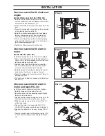
Page 17: ... the remaining guide wheels 4 Position the four rail guards FIG 27 above the wheel Saw Carriage Adjustment FIG 26 The saw carriage is aligned on the rails by fitting its lower guide wheels and rail guards The lower guide bearings have the task of preventing the saw carriage from tilting and the rail guards keep the rails and the saw carriage s wheels free from dirt and the like Assembled on the sa...

Page 18: ...h correspond with the direction of rotation according to the arrow A 2 Position the bar and thread the chain around the bar CAUTION Ensure that the tip of the tension screw s nut B fits into the hole on the bar 3 Install the guide C and loosely tighten the two bar bolts just so that there is no play on the bar 4 Adjust the chain using the tension screw Tighten to a torque of 30 Nm 5 The direction ...

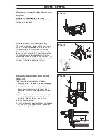
Page 19: ...n D and the log bolster Set the scale pointer so that the scale has the same value 4 Bolt on the scale pointer 5 Check that the saw chain moves freely over the long E and short C log supports when the red mark can be read on the scale Install throttle and cable FIG 33 The throttle and lever are installed in the chain saw s handle The loop A is positioned inside the handle The washers B and C are s...

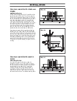
Page 20: ...t it is parallel with the log bolsters FIG 36 Adjust using the outer adjustment nut until the distance between the log bolsters and the bar is the same along the entire length of the bar Then tighten the locking nuts Check the setting once more To achieve the optimum result it is very important to ensure that these settings are performed accurately This prevents the timber being at an angle or the...

Page 21: ...ion when handling fuel Use good quality unleaded or leaded petrol The lowest octane recommended is 90 If you run the engine on a lower octane grade than 90 so called knocking can occur This gives rise to a high engine temperature which can result in serious engine damage CAUTION The one man sawmill which is equipped with a two stroke engine must always be run on a mixture of petrol and two stroke ...

Page 22: ...ure Add the remaining amount of petrol Mix shake the fuel mixture thoroughly before filling the saw s fuel tank Do not mix more than max one month s supply of fuel If the saw is not used for some time the fuel tank should be emptied and cleaned Fuelling 1 Clean around the fuel cap 2 Open the fuel cap slowly so that any excess pressure is released 3 Tighten the fuel cap carefully after fuelling Cle...

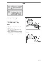
Page 23: ...d engine is started as follows 1 Read through the operator s manual for the chain saw carefully and make sure you understand it before attempting to start the chain saw 2 Set the stop button to the start position 3 Pull out the choke When the choke is pulled out the throttle valve is automatically set in the start throttle position 4 For other operation see the chain saw operator s manual FIG 38 F...

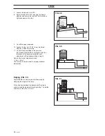
Page 24: ... be stopped using the red stop button 32 3 Check the chain direction see FIG 29 FIG 42 37 29 27 31 30 A 27 16 29 32 37 B Starting the electric sawmill with feed FIG 42 1 Check that the power cable is connected correctly 2 Keep the green start button 29 pressed in using your right hand Then press the black safety switch 37 using your left hand When the sawmill has started the safety switch must be ...

Page 25: ...Roll the log up against either the long or the short log support depending on the timber dimensions than 300 mm to the end of the rails than 500 mm to the start of the rails This means that when using two rail sections the maximum log length is 5200 mm 3 Raise the log using the log lifter B so that the log s core is horizontal 4 Lock the log in position with the log lock D USE FIG 43 FIG 44 ...

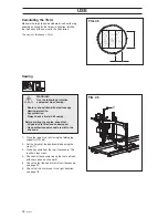
Page 26: ... chain runs in the right direction see page 18 Calculating the Yield Measure the log s top end and determine how the log should be utilised for the timber in question Include the thickness of the saw cut in the calculation The saw cut thickness 7 mm WARNING Use the following protective equipment when sawing Boots or shoes fitted with steel toecaps Hearing protection Eye protection Always have a fi...

Page 27: ...l Engine 1 Start the engine See page 23 Starting the Electric Motor 1 Start the electric motor See page 24 Sawing 2 Move the saw carriage forwards and cut off the sapwood 3 Remove the sapwood 4 Loosen the log turn it 180 lower the height adjuster B and secure the log 5 Set the required cutting height using the height adjustment crank 11 This determines the width of the board 6 Cut off the sapwood ...

Page 28: ...o the previous instructions Remember to compensate for the thickness of the bandsaw blade for each adjustment of the bandsaw blade s height Data for the height adjustment crank 1 turn 5 mm The scale can also be used for varying standard dimensions Edging FIG 51 Several boards can be edged simultaneously by clamping them against the stop Place a batten between the boards and the stop in order to ke...

Page 29: ...r has a setscrew installed in the end of the drive shaft The task of the screw is to prevent the clutch drum from unscrewing in the event the sawmill is started in the wrong direction CAUTION The screw and its washer must be unscrewed before the clutch drum can be removed The clutch drum has left hand threads The clutch drum is equipped with ring sprockets replaceable The clutch drum has a needle ...

Page 30: ... should be sharpened regularly to give optimal performance During normal sawing of most species of wood this should be done at intervals of approximately 2 hours effective cutting time i e the time that the saw chain is actually working The chain should be sharpened more frequently when cutting those species of wood with a high sand content A special file gauge article no 504 98 16 78 is available...

Page 31: ...cks C on both pulleys 7 Screw the motor into position and tension the belt with the tension screw B Check the belt tension with your thumb D and install the belt guard A B C D A E 10 mm Adjusting the saw saddle The saw saddle s plastic guides may need to be adjusted after a few hours of use This is done as follows 1 Slacken off the three mounting nuts 2 Screw in the two adjustment screws until the...

Page 32: ...s manual See also weekly and monthly maintenance for the chain saw Weekly maintenance 1 For chain saw maintenance see the chain saw operator s manual 2 Check the belt tension and adjust if required See page 31 3 Clean around the rails Remove sawdust bark and wood chips to facilitate handling of the chain sawmill Monthly maintenance 1 Check the clutch function see page 29 2 Check cables and connect...

Page 33: ... equipment Chain Chain type Pitch inches Track width inches mm Drive links Part no chain 16 Part no chain 20 Bar Part no bar 16 40 Part no bar 20 50 Capacity Max log height mm Max log width mm Max log length mm 2 rail sections Chain speed chain saw engine m s Chain speed electric motor m s Setting options Height adjustment crank turns mm Index plate resolution mm 50 Hz 5 5 kW 2855 r min 11 0 11 1 ...

Page 34: ...d SM 2186 with serial numbers 02 100001 02 5200100 meet the standards prescribed in the COUNCIL S DIRECTIVES of 22 June 1998 relating to machinery 98 37 EC appendix IIA of 3 May 1989 relating to electromagnetic compatibility 89 336 EEC and applicable supplements of 19 February 1973 relating to electrical equipment 73 23 EEC For information regarding noise emissions see the Technical Data chapter T...

Page 35: ......

Page 36: ...2003W50 z x 6 108 89 11 26 ...

Reviews: