CHAPTER5: Troubleshooting
19
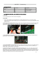
5.1 Error Code List
Mode Name
Error Code
Description
5.5AT
E1
RPM was not detect
E2
Sudden accelerate
5.9AT
NA
NA
5.2
TROUBLESHOOTING – NO POWER TO THE CONSOLE
1) SYMPTOM:
a. Turn on the power switch, but the console will not light up.
2) SOLUTION:
Please note the MCB in this model does NOT have an LED indicating the power is on. This means voltage
measurements must be taken to find the cause of a non-functioning console. Continue with each step below until the
problem is found.
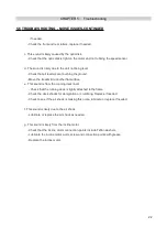
a.
Check power at the console.
Measure power on pins 1 and 2 on the console cable where it connects to the console.
These are the same 2 wires labelled “12V and GND” on the console PCB as seen in the red circle below. If there is
approximately 12 VDC on pins 1 and 2, replace the console. If not, continue to step b.
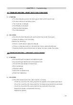
b.
Check the MCB is providing power to the console.
Measure the pins in the yellow circle in the picture below. If
approximately 12 VDC is measured at these pins, replace the console cable.
c.
Check that the MCB is receiving 120 VAC.
Measure the black and white wires which connect to the MCB. If there is
approximately 120 VAC (+/- 15 VAC) on these wires, replace the MCB. As previously mentioned, this MCB has no
indicator LED to indicate the MCB is receiving power.
d.
Check the outlet, power cord, breaker, switch, and internal wiring.
If there was no AC voltage measured at the
MCB in step 3, then there is a problem with the AC voltage getting to the MCB. Carefully check the building breaker,
electrical outlet, power cord, treadmill breaker, treadmill power switch, and treadmill internal wiring to determine why AC
voltage is not being supplied to the MCB. The technician must verify what is not functioning with voltage and continuity
checks before ordering any parts to avoid sending unnecessary parts.
Summary of Contents for AFG 5.5AT
Page 2: ...2 Product Browse 5 5AT ...
Page 3: ...3 Product Browse 5 9AT ...
Page 6: ...CHAPTER 1 Serial Number Location 6 SERIAL NUMBER ...
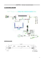
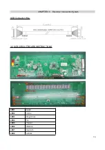
Page 11: ...CHAPTER 3 Electrical Connection System 11 3 1 ELECTRICAL DIAGRAM 5 5AT Console Wire ...
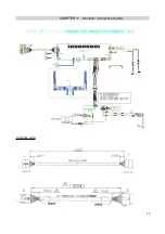
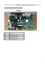
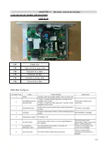
Page 13: ...CHAPTER 3 Electrical Connection System 13 Console wire ...
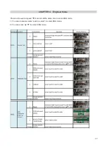
Page 18: ...CHAPTER4 Engineer Mode 18 ...


