


85-03-00954
33 |
P a g e
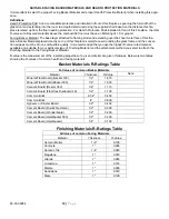
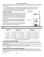
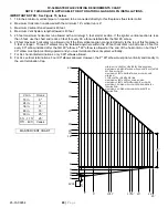
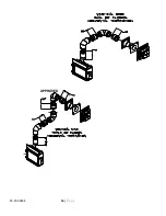
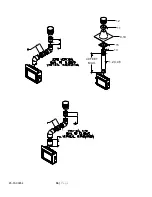
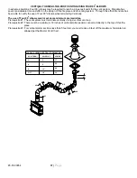
VERTICAL RISE HORIZONTAL TERMINATION
The minimum vertical section required to be connected directly to the starter adapter on this fireplace is 60 inches when
used with a maximum horizontal run of 25 ft. If the total length of the vertical sections connected directly to the starter
adapter on this fireplace is between 5 feet and 17 feet, you are allowed a maximum 25 feet horizontal run. This fireplace
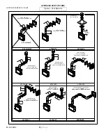
provides a maximum flexibility in the use of 90
0
elbows when more than 5 feet of vertical starter section is connected to
the starter collar. If 5 feet or more vertical section is connected to the starter collar, you may use three 90 degree elbows
and 25 feet of horizontal pipe sections for Horizontal Terminations. For other venting configurations within these maximum
limits, see Master Venting Chart.
Combined total length of all pipe sections in the vent system shall be less than 40 feet.
NOTE:
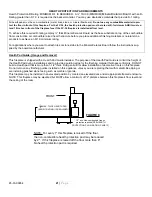
The horizontal run of vent pipe must have a ¼" rise for every 1' of run toward the termination. Never allow the
vent to run downward. This will cause high temperatures and the possibility of a fire.
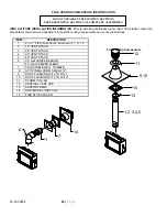
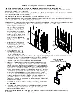
This FV-34 Fireplace must be installed by a qualified Mendota service person
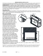
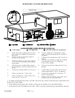
1. Position fireplace in desired location. See Figure 13 for guidelines on proper vent cap placement on exterior of home.
Check to determine if wall studs are in the way when vent system is attached. If this is the case you may want to ad-
just the fireplace location.
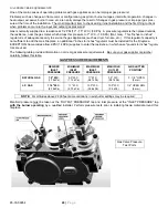
2. Locate where vent pipe will pass through any ceilings and will penetrate the outside wall. Since vent pipe sections
"overlap" we suggest pre-assembling and measuring the total vent pipe run so you can more accurately locate the
point where the vent pipe will penetrate the outside wall (See Figure 13). Be sure all vent components are properly
twist locked and leak-proof. Be sure 1000
º
sealant is used in the inner pipe joints of all pipe sections manufactured
by Simpson DuraVent.
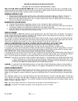
3. Cut and frame a 9” wide x 10”” high opening in the outside wall openings and 9” x 9” opening in ceiling openings. The
outside wall hole must be positioned so the vent system will have a ¼" rise per foot on horizontal runs AND be per-
pendicular to the wall. The height of the opening must be located to meet all building codes and not allow the termi-
nation to be easily blocked or obstructed. A ceiling fire stop spacer is required at any floor (ceiling) opening.
4. The horizontal pipe must end flush with the exterior wall of the home. Horizontal pipe will require a proper support
every 3 ft. of vent pipe. THERE MUST BE A MINIMUM OF 1" CLEARANCE TO COMBUSTIBLES FROM ALL VENT
PIECES ON THE SIDES AND BOTTOM AND 2" ABOVE HORIZONTAL RUNS).
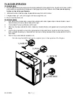
5.
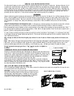
A wall thimble must always be used when penetrating combustible wall materials
.
NOTE:
Combustible wall thickness must be 4" to 8" maximum.
6. From the exterior of the home, slide the horizontal vent cap over the end of the horizontal pipe and tightly secure the
vent cap to the wall with screws. Seal with high quality caulking around the outer perimeter of the Vent Cap.
NOTE:
Venting terminal (Vent Cap) should not be recessed into wall or siding.
NOTE:
DO NOT SEPARATE TELESCOPING SECTIONS.
THEY MUST BE USED AS COMPLETE ASSEMBLIES.
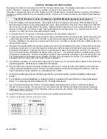
V H
18” 6”
24” 4’
3’ 11’
4’ 18’
5’- 17’
25’
For V greater than 17’,
see Master Venting
Chart


