


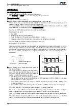
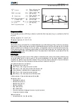


STP
M
Set point
TVD
Phase input/output time
variation differential
RBM Control band
HTON Stage activation maxi‐
mum time delay
NZ
Neutral zone
LTON Stage activation mini‐
mum time delay
EOW
T
Water temperature at
exchanger outlet
HT
OFF
Stage deactivation max‐
imum time delay
DonZ Compressor
ON
zone
LT OFF Stage deactivation mini‐
mum time delay
DoffZ Compressor off zone
t
Time
Compressor rotation
The controller provides a FIFO type rotation in which the first compressor to go on will also be the first
to go off.
Start-up sequence: C1, C2, C3, C4.
Stoppage sequence: C1, C2, C3, C4.
HP prevent
When this function is enabled, the controller attempts to avoid the blockage of the unit due to excessively
high pressure. When said pressure reaches a preestablished value near the off pressure, the controller
speeds up the fans to a maximum (if in cool cycle), or slows them down to a minimum (if in heat cycle).
If the operating pressure continues getting close to the HP Prevent pressure, the controller turns off a
compressor in the tandem of the affected circuit. The parameters of said function are accessed from the
CONDENSATION menu.
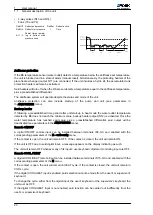
Defrost cycle
If the evaporating pressure of one of the systems remains below the value set for starting defrost during
an accumulated period of time equal to the period established as the delay between defrosts,
simultaneous defrost of all unit coils is started. The cycle ends once the pressure set as end defrost is
reached, or at the end of the time period set as maximum duration of the cycle.
The defrost sequence is as follows:
1. Compressor are turned off
2. After 15 sec., the 4-way valves are inverted
3. After 45 sec., the compressors start with the fans off
4. Once defrost is completed, the compressors stop
5. After 15 sec., the 4-way valves are inverted
6. After 45 sec., the compressors and the fans start
Control sensors: Pressure transducers B3 and B4.
Parameters used:
• Simultaneous defrost.
• Defrost start pressure
• Defrost end pressure
• Defrost call delay
• Max. defrost time
• Min. defrost time
• Forced compressor stoppage time due to cycle inversion
• 4-way valve inversion delay
Affected outputs:
• Compressors (N1, N2, N3 and N4)
User manual
1
General description of the unit
1.1
19


