


There is no intent for the user to perform any maintenance tasks on the HVAC unit.
D A N G E R
It is strictly prohibited for the user to carry out any maintenance or upkeep tasks on the HVAC unit.
This appliance is not destined for use by people (including children) with limited physical, sensorial or
mental capacities, or without adequate experience or knowledge, unless they have received instructions
or been supervised in the use of the appliance by an individual responsible for their safety.
Children must be supervised at all times to ensure that they do not play with the appliance.
Only trained Johnson Controls Inc. personnel with the necessary means and tools may carry out
maintenance and upkeep work on the unit.
Trained personnel must be aware of the health and safety regulations and procedures applicable to
HVAC units. They should also be aware of general procedures and those applying specifically to this
unit.
Contact a Johnson Controls Inc. Authorised Technical Assistance Service for scheduled maintenance
on this unit.
PRODUCT DISPOSAL
According to Directive 2002/96/EC of the European
Parliament and of the Council of 27 January 2003, the
presence of the symbol on the product or in the
documents included with the product indicates that
this product is classified, according to current law, as
an electrical and electronic device and, therefore, this
product cannot be dealt with at the end of its working
life as domestic or urban waste.
The product must be taken to collection points for the
recycling of waste electrical and electronic
equipment.
The appropriate management, reuse, assessment
and recycling of these products protect human health and the environment.
User manual
1
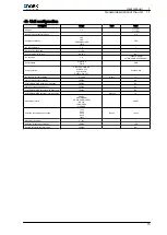
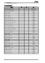
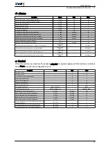
General description of the unit
1.1
25