Johnson Controls VA-77 Series Product Bulletin Download Page 3

3

PB_VA-7700_Electricl Valve Actuators_02 2011

Operation

Floating■models■

Connections

Actuator■Stem

1-2

Extends

1-3

Retracts

Proportional■models■

(0…10■VDC■or■0(4)…20■mA)

The VA-77x6 provides a proportional stroke corresponding to the 
control signal.

Following control signals are defined as standard:
0…10 VDC
0…5 VDC
5…10 VDC
0…20 mA
4…20 mA

Action■

(DIP■switch■set)

Input■

control■

signal

Actuator■

Stem

Position■at■

control-signal■

failure■*

Direct■(DA)

Increases 

Decreases

Extends 

Retracts

Selectable* 

Selectable*

Reverse■(RA)

Increases 

Decreases

Retracts 

Extends

Selectable* 

Selectable*

* "Signal failure" position pre-set does not operate when 0…20 
mA control is selected

.

The action mode, 

DA

 (direct acting) and 

RA

 (reverse acting) 

is set through the DIP switches 

(see paragraph "DIP switch 

settings")

.

The actuator control signal has a buffer zone, at each end of the 
span, of 0.3 V or 0.3 mA.  
This ensures definite valve close-off.

Control■signal■failure■pre-set■position■

(not functional with 0…20 mA control selected)

A control-signal failure on proportional models will cause the 
actuator to automatically move the stem to a (via DIP-switches) 
pre-selected position (100% extended or 100% retracted).

Auto■Calibration■procedure■with■standard■

input■signal■ranges.

The standard control signals are selected by setting DIP switches 
3 and 4 switch 

(see paragraph "DIP switch settings").

It is recommended to set the actuator to the desired control signal 
and action before fitting to the valve 

(see paragraph "DIP switch 

settings").

Power must be connected before the auto-calibration cycle can 
be started.

Procedure:■Actuator■is■mounted■on■valve.

•  Verify that with the stem fully retracted, there is a minimum 

distance of 1 mm between the top of the actuator stem nut and 
the stem guide bush in the actuator motor housing base plate. 
If necessary correct the distance by adjusting the actuator / 
valve stem connection.

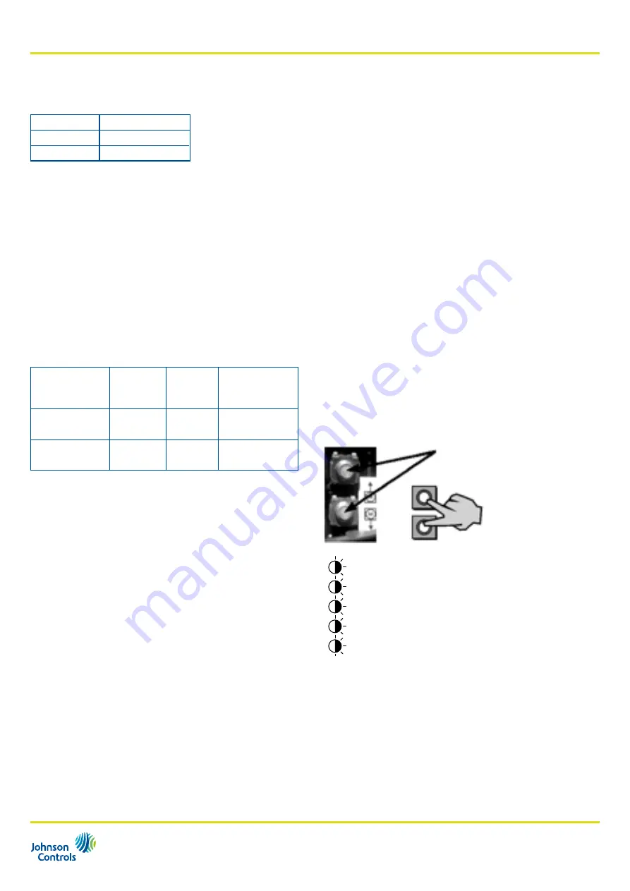
•  To start the auto calibration cycle, push both calibration buttons 

for at least 5 seconds. The actuator will make a full cycle to 
detect the stem extended and retracted limits.

•  When the auto calibration cycle is completed the LED 

stop flashing, the actuator stem moves to the position that 
corresponds to the control signal and the five LED indicate the 
stem position.

•  When the control signal changes the actuator stem moves to 

the new position this is indicated by one flashing LED. The LED 
stops flashing when the position corresponding to the control 
signal has been reached.

Note:

 When ever the actuator is newly placed on a valve, 


auto-calibration must be carried out.

Calibration buttons

> 5 sec

During auto-calibration cycle all five 

status indication LED flash simultaneusly

Summary of Contents for VA-77 Series

Page 1: ...des Enables sequence control Magnetic clutch Provides constant output force for close off of valves and protects motor in stall conditions Control Signal failure stem to pre determined position Actuat...

Page 2: ...ectrical and Mechanical VA 7746 8201 24 VAC Electrical and Mechanical These actuators can be combined with the following valve ranges VG7000 Series Threaded Valves Female and male threaded valves Thes...

Page 3: ...ranges The standard control signals are selected by setting DIP switches 3 and 4 switch see paragraph DIP switch settings It is recommended to set the actuator to the desired control signal and actio...

Page 4: ...um and the maximum control signal values are stored in the memory of the actuator When the auto calibration cycle is completed the LED stop flashing the actuator stem moves to the position that corres...

Page 5: ...VDC 3 0 10 VDC 4 4 3 5 10 VDC 5 4 6 Direct Acting mode 3 Free Range 7 Electrical manual override off 4 8 Signal failure position pre set Up 5 0 20 mA 5 4 20 mA 6 Action 6 DA 6 RA 7 Electrical Manual...

Page 6: ...nd the LED indicate a general alarm code If the problem is cleared however the actuator continues normal function Fault mode If the actuator enters fault mode the LED will flash as shown The indicatio...

Page 7: ...tion The controller 0 10 V output can operate several actuators with built in electronic positioner The number of actuators that can be linked to a single controller depends on the controller s active...

Page 8: ...d lead to an abnormal operating condition that could cause personal injury or damage to the equipment or other property other devices limit or safety controls or systems alarm or supervisory systems i...

Page 9: ...g models 230 VAC supply VA 7746 xx01 Proportional models 24 VAC supply WARNING Equipment Damage Hazard On 24 V models with manual override it is not permitted to connect voltages greater than 24 V to...

Page 10: ...ors_02 2011 VA 7700 xx01 Floating models 24 VAC supply VA 7700 xx03 Floating models 230 VAC supply VA 7706 xx01 Proportional models 24 VAC supply Wiring Diagrams Models without mechanical manual overr...

Page 11: ...11 PB_VA 7700_Electricl Valve Actuators_02 2011 Dimensions in mm VA 77xx 82xx 87 90 VA 77xx 10xx A 25 mm VA 770x actuators without manual override A 80 mm VA 774x actuators with manual override...

Page 12: ...250 0 4 20 mA Resolution 0 5 up to 200 steps on 20 mm stroke Feedback ratings max 2mA at 0 10 VDC 5 k Manual contact micro switch max load 2A Resistive 1A Inductive 24 VAC 24 V switch 2A Resistive 1A...

Reviews: