background image

Maintaining Cluster Communication

3–10

iSTAR Ultra Installation and Configuration Guide

Maintaining Cluster Communication

Maintaining cluster communications involves establishing and maintaining connections via 

the primary communication path or (optional) secondary communication path. If the primary 

connection is lost, the secondary communication path is used to re-establish cluster 

communications. 

Single Master Configurations

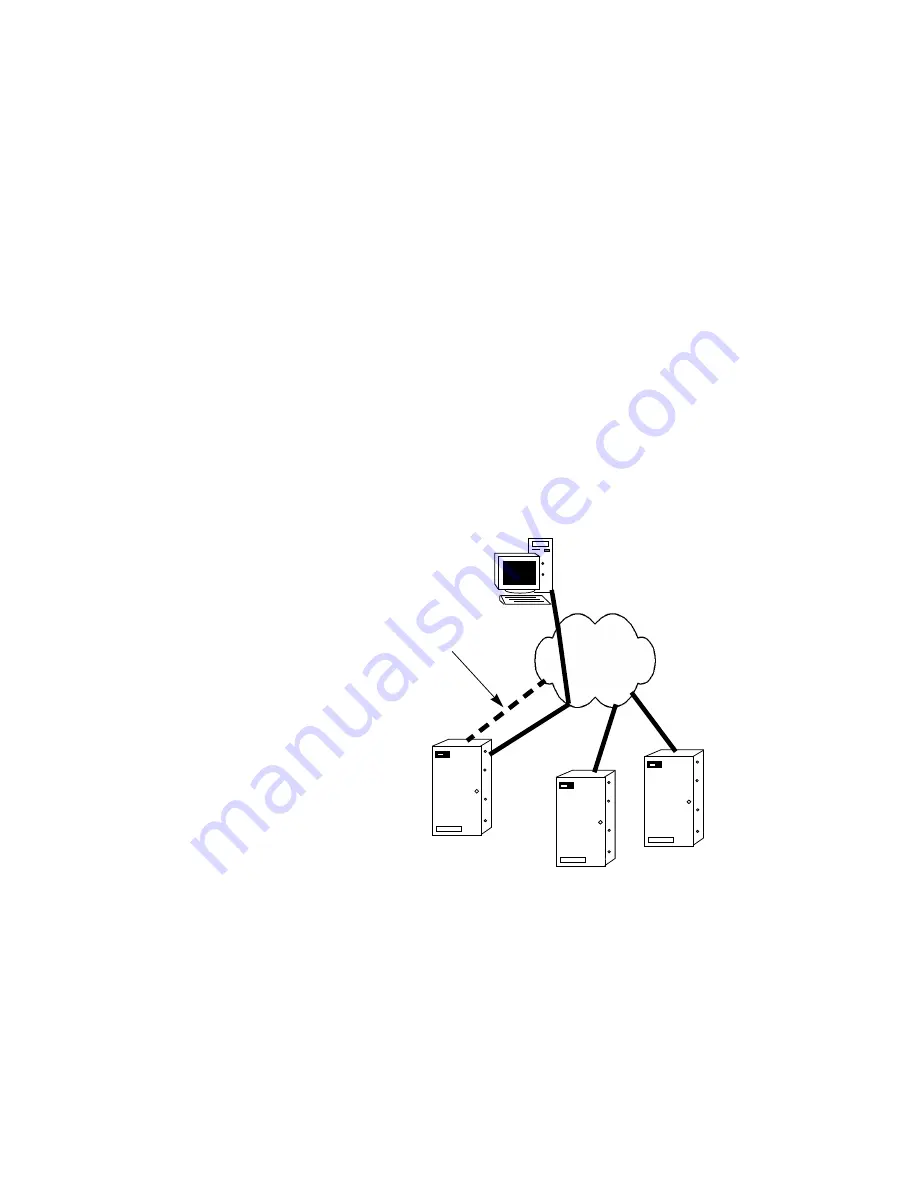
If a configuration with a single master loses its connection with the host, as shown in 

Figure 3-7 on 

page 3-10

:

Cluster members continue to communicate with the master.

The master continues to pass cluster members’ messages to the host.

The master uses the secondary path to communicate with the host.

Example:

If the secondary path is an alternate network connection between the master and host, the 

master uses the alternate network to communicate with the host.

Figure 3-7:  

Communication Failure with Single Master Configuration

Host

Ultra Master

Network Failure

Member

Member

Summary of Contents for tyco iSTAR Ultra

Page 1: ...Software House iSTAR Ultra Controller Installation and Configuration Guide Part Number 8200 1760 02 Revision B0 September 2019...

Page 2: ...ved JOHNSON CONTROLS TYCO and C CURE 9000 are trademarks and or registered trademarks Unauthorized use is strictly prohibited Product offerings and specifications are subject to change without notice...

Page 3: ...iSTAR Ultra 1 6 Main Features 1 7 Processor 1 7 Storage 1 7 Power 1 7 RM Wiegand Signaling Readers per ACM 1 7 Aperio Hubs and Readers per GCM RS 485 Comm Port 1 8 I O per ACM 1 8 I O per GCM 1 9 Comm...

Page 4: ...stic Enclosure 2 18 Requirements 2 18 Metal Enclosure 2 19 Chapter 3 iSTAR Ultra Network Topology iSTAR Ultra Network Topology 3 2 LAN and WAN Configurations 3 2 Gateways and Firewalls 3 2 Local Addre...

Page 5: ...6 GCM Power J4 4 7 J14 SD Card 4 7 Ports 4 8 RS 485 1 and 2 J12 and J13 4 8 USB Type A J8 and J9 4 8 USB Micro A B J7 4 8 RS 232 Diagnostic Port P4 4 8 COMM Board Connector J15 4 8 Visual Indicators...

Page 6: ...I Scenarios 5 24 FAI Modes 5 24 FAI without Latch 5 24 FAI with Latch followed by Key Unlatch 5 25 F and K input Supervision 5 26 State of F K and Relay Drive 5 27 iSTAR Controller Status Tab 5 28 Rea...

Page 7: ...enance LCD Message Display 8 2 Displaying Status Messages 8 3 Setting LCD Status Message Display 8 3 Diagnostic Tests 8 4 Hardware Test 8 4 Card Reader Diagnostics 8 5 Output Diagnostics 8 5 Output Ch...

Page 8: ...Table of Contents viii iSTAR Ultra Installation and Configuration Guide...

Page 9: ...system users The guide describes procedures for installing configuring using and maintaining the iSTAR Ultra controller The guide assumes that you are a certified C CURE 9000 Technician and C CURE 900...

Page 10: ...A screen element or name Regular italic font Indicates a new term or a book title text Indicates a variable NOTE Indicates a note Notes call attention to any item of information that may be of special...

Page 11: ...anuals if you copy the appropriate PDF files from the C CURE 9000 installation media Manuals CCURE folder The available C CURE 9000 and Software House manuals are listed in the C CURE 9000 Installatio...

Page 12: ...House accepts service calls only from employees of the Systems Integrator of Record for the installation associated with the support inquiry Before Calling Ensure that you Are the Dealer of record fo...

Page 13: ...94 53 South Africa 27 211 003 882 Russia 81080020521031 Turkey 00800 31923007 UAE 800 03107123 Bahrain 800 04127 Asia Pacific Hours 9 00 a m to 5 00 p m CST Toll Free 800 CALLTYCO or 800 2255 8926 Dir...

Page 14: ...Preface xiv iSTAR Ultra Installation and Configuration Guide Venezuela 58 212 720 2340 Buenos Aires 54 11 5199 3104 Santiago de Chile 56 2 3210 9662 Sao Paulo 55 11 3181 7377...

Page 15: ...ed iSTAR Ultra training that you are familiar with networking concepts and hardware installation and you are using firmware v6 6 B or higher In This Chapter Overview 1 2 General Control Module 1 2 Acc...

Page 16: ...lt in diagnostics Four USB ports to communicate with the Access Control Modules ACM and import encryption keys One Micro A B port For future use Access Control Module The ACM is a special purpose Acce...

Page 17: ...er and whichever reader power is used are limited to a total of 1 5 Amp See Chapter 5 Access Control Module ACM for more information IP ACM Ethernet Door Module The IP ACM Ethernet Door Module v2 prov...

Page 18: ...f Mounting The iSTAR Ultra and its components can be installed in a wall mount enclosure or in separate rack mount enclosures Wall Mount Enclosure Figure 1 1 on page 1 4 shows a photograph of the iSTA...

Page 19: ...iguration Guide 1 5 Rack Mount Enclosures Figure 1 2 on page 1 5 shows the GCM in a rack mount enclosure Figure 1 2 GCM Rack Mount Enclosure Figure 1 3 on page 1 5 shows the rear of the GCM rack mount...

Page 20: ...and Configuration Guide iSTAR Ultra Figure 1 4 shows the iSTAR Ultra enclosure The bright power LED will shine through the Power decal when the door is closed The bright LED will extinguish when the...

Page 21: ...voltage 12 or 24V with external DC supply Each wet relay is limited to 0 75A at 12 or 24V Each Primary dry relay is limited to 5 0A at 12 or 24V Each Secondary dry relay is limited to 1 0A at 12 or 24...

Page 22: ...exist to the extent that the configured Aperio Readers are less than 32 I O per ACM 24 general purpose inputs 16 general purpose relays Dry or wet contact settable per relay by jumpers 4 pin connecto...

Page 23: ...put is true FAI activates relays that are enabled for FAI by individual enable switches The Primary relays large mounted in sockets can be configured to activate when the FAI signal goes true Onboard...

Page 24: ...one ACM 0312 5015 01 and one enclosure 0505 0411 01 USTAR016 Contains one GCM 0312 7101 01 two ACM 0312 5015 01 and one enclosure 0505 0411 01 USTAR SD Unencrypted SD card with firmware v6 6 9 Subasse...

Page 25: ...on This chapter provides information about site requirements and installation for the iSTAR Ultra hardware In This Chapter Pre Installation Planning and Requirements 2 2 Power Requirements 2 7 Other I...

Page 26: ...bles Types of Mounting The iSTAR Ultra and its components can be installed in a wall mount enclosure or in a separate rack mount enclosure Environmental Requirements Table 2 1 on page 2 2 lists the iS...

Page 27: ...ACMs When disconnecting wiring disconnect ground wires last to provide maximum protection to the equipment and personnel Wiring Requirements The iSTAR Ultra Ethernet connections are GCM Onboard Ethern...

Page 28: ...inimum 22 AWG stranded twisted pair cable for monitor points supervised inputs DSMs and REXs Use Belden 9462 or equivalent b Check wire lengths to verify that voltage drops are acceptable Calculations...

Page 29: ...able 2 3 Heat Dissipation Configuration Power Dissipated in Enclosure BTU hour Rack GCM 17 88 Watts 61 0 Rack ACM 6 Watts 20 5 Wall GCM and 1 ACM 23 88 Watts 81 5 Wall GCM and 2 ACMs 29 88 Watts 102 0...

Page 30: ...4 inch 6 4 No Anchor Concrete Screws 10 x 1 1 4 inch 4 Super Hold Plastic Anchors Wood sheet metal screws 10 x 1 1 4 inch 10 x 1 1 4 inch 6 Toggle Bolts bolt included only for keyholes 10 24 x 1 1 4 i...

Page 31: ...s measured 1 5A maximum each Wiegand AUX 12 Vdc 800MA maximum each Primary Wet Relay Out 0 30 Vdc 0 75A maximum each Secondary Wet Relay Out 0 30 Vdc 0 75A maximum each Secondary Dry Relay Out 0 30 Vd...

Page 32: ...8 10 1 ACM with 5 Wiegand RS485 Aux load 12 9 5 12 1 ACM with 6 Wiegand RS485 Aux load 12 11 15 1 ACM with 7 Wiegand RS485 Aux load 12 12 5 29 1 ACM with 8 Wiegand RS485 Aux load Lock 1 and 2 Power R...

Page 33: ...5 Loads 1 ACM with 7 Wiegand RS485 Aux load 12 18 99 25 1 GCM with 2 RS 485 Loads 2 ACM with 9 Wiegand RS485 Aux load 12 23 49 30 1 GCM with 2 RS 485 Loads 2 ACM with 12 Wiegand RS485 Aux load 12 27 9...

Page 34: ...ALLATIONS The iSTAR Ultra is not provided with backup power An external power supply must be provided with the following characteristics UL 603 or UL 294 Listed Minimum four hours of standby power Tyc...

Page 35: ...lding a a grounded surface for three seconds Wear a grounding wrist strap and stand on a grounded static mat Reduce movement during installation to reduce static buildup Make sure work area is safegua...

Page 36: ...kup It does not affect how iSTAR Ultra treats power loss iSTAR Ultra still watches for input voltage to move outside of the normal operating voltage range and at that time will perform a full state an...

Page 37: ...RM with Indala proximity RM1 P RM2 PI 80 mA max RM with Indala proximity and LCD RM2L PI 180 mA max RM with HID proximity RM1 PH RM2 PH 250 mA max RM with HID proximity and LCD RM2L PH 250 mA max RM...

Page 38: ...with the iSTAR Ultra All other readers in Table 2 10 are UL Listed compatible readers that can be used with the iSTAR Ultra Table 2 10 Software House Reader Power Requirements continued Reader Model...

Page 39: ...e rated at 0 30 Vdc but are usually 12 Vdc or 24 Vdc In some installations the locks can be two 12 Vdc or two 24 Vdc or either combination of both voltages The enclosure has knock outs for installing...

Page 40: ...ll the three lower mounting screws and the remaining top mounting screw in between the two keyhole mounts 7 Attach the conduit couplings to the knockout openings as needed to comply with local code re...

Page 41: ...ra as a Rack Mount Elevated Operating Ambient If installed in a closed or multi unit rack assembly the operating ambient temperature of the rack environment may be greater than room ambient Verify tha...

Page 42: ...M Requirements The anchoring system must be capable of sustaining 25lb 11 4kg This weight does not include the cables The cables are protected by use of conduit which is metal plastic or flexible cabl...

Page 43: ...se Refer to Figure 2 2 on page 2 18 for dimensions and hole pitch for mounting 3 Secure the IP ACM Ethernet door module to the right of the enclosure 4 Fit and connect all customer cables 5 Secure the...

Page 44: ...re to selected wall or support surface using holes provided in the enclosure s base Refer to Table 2 3 for dimensions and hole pitch for mounting 3 Fit and connect all customer cables See the IP ACM E...

Page 45: ...o site requirements You must understand iSTAR Ultra topology and customer requirements to ensure the correct layout connections and configuration of iSTAR Ultra components In This Chapter iSTAR Ultra...

Page 46: ...e master controller automatically accepts a translated IP address if one is assigned from a remote host or from an attached Network Address Translator Generally the TCP IP ports listed in Table 3 1 on...

Page 47: ...TAR Ultra configuration To configure this cluster the System Manager is in the branch office Use PING to check communication to the exposed translated address from the Corporate Office Use the ICU to...

Page 48: ...DNS servers complement DHCP address assignment by providing name to IP address mapping Fully Qualified Domain Names Configurations where IP addresses are subject to change leased DHCP addresses for ex...

Page 49: ...rypted mode S1 1 True iSTAR Ultra LT Encryption mode S1 1 ON iSTAR Edge 1 2 or 4 reader models iSTAR eX 4 or 8 reader models Non Encrypted clusters can contain the following controllers iSTAR Ultra If...

Page 50: ...n and Configuration Guide Figure 3 3 Cluster Member Communications Host Hub 1 4 3 2 Master Cluster Member A Cluster Member B Ethernet Network 1 4 3 2 Cluster Member B Cluster Member A Master Host Clus...

Page 51: ...ler Figure 3 4 shows primary and secondary communications using a single master Figure 3 4 Single Master Configuration Single Master Configurations Table 3 2 on page 3 7 shows the configuration option...

Page 52: ...s Cluster members do not communicate with the host directly they communicate with the host through the master Connections are established in the following bottom to top order Cluster members are respo...

Page 53: ...unications path that is used by a cluster if a communications failure occurs on the primary path Figure 3 6 on page 3 9 shows an example of a secondary path on a single master configuration using two...

Page 54: ...ingle Master Configurations If a configuration with a single master loses its connection with the host as shown in Figure 3 7 on page 3 10 Cluster members continue to communicate with the master The m...

Page 55: ...to a cluster the controller becomes a cluster member One controller can comprise a cluster You can configure a controller as its own cluster by configuring a cluster that includes only the controller...

Page 56: ...parameters for establishing and maintaining the primary path Primary Communication Guidelines Follow these guidelines when configuring a primary path Every cluster must have a master Only one master i...

Page 57: ...ion and Configuration Guide 4 1 4 General Control Module GCM This chapter describes the GCM switches buttons jumpers LEDs and the LCD In This Chapter General Control Module 4 2 Switches 4 3 Ports 4 8...

Page 58: ...General Control Module 4 2 iSTAR Ultra Installation and Configuration Guide General Control Module Ultra SE Pro Mode D0...

Page 59: ...the Host after the reboot SW7 should be used to Reset to Factory Default by changing the Rotary Switch SW3 to D and pressing SW7 See Table 4 1 on page 4 4 for Rotary Switch descriptions To Clear Memor...

Page 60: ...isplay card data from last card read 2 second LCD display fast mode 3 Display supervised input changes 2 second LCD display slow mode 4 Display supervised input changes 1 second LCD display fast mode...

Page 61: ...re stored in RAM The database and transactions are not backed up on the SD The default setting is OFF S1 3 For future use S1 4 Not used in the iSTAR Ultra Controller RS 485 Terminators SW5 and SW6 The...

Page 62: ...s reported its battery as low Wired in from external power source Shares the connector and Ground pin with AC Fail Normally closed dry relay contacts are required Configured on the host as unsupervise...

Page 63: ...n 1 on the left is 12 Vdc pin 2 is GND J14 SD Card Located on the back of the GCM to the left of the SOM near the Hard Reset switch This non volatile memory is where backups are stored NOTE The Tamper...

Page 64: ...n RS 232 Diagnostic Port P4 Software House Tech Support and Engineering use for troubleshooting COMM Board Connector J15 Not supported Future option Visual Indicators Power DS1 and DS2 Indicate that p...

Page 65: ...are extinguished when the unit detects input power failure and enters sleep mode to minimize power consumption Users have the ability via the host to configure LCD back light and LEDs other than Power...

Page 66: ...Visual Indicators 4 10 iSTAR Ultra Installation and Configuration Guide...

Page 67: ...is chapter explains the ACM switches buttons jumpers LEDs and the LCD The wiring of various external connections are also shown In This Chapter Access Control Module 5 2 Inputs 5 18 FAI Connections 5...

Page 68: ...evices such as a PIR or Motion Sensor FAI Activate Switch Only for Primary Relay Two Relays One Primary and one Secondary Primary Relays Field replaceable mounted in a socket Physically larger than th...

Page 69: ...ion Guide 5 3 Figure 5 1 ACM Layout Figure 5 2 on page 5 4 indicates all of the components of sections 1 and 8 This pair is typical of the other 3 pairs It also shows the Power IN ports and the FAI in...

Page 70: ...and 8 are indicated on most of the components The jumper technique for wet or dry relays is shown on the left The power connector labeled Reader is used for the reader and the logic The next 2 sets a...

Page 71: ...th MCUs It should only be used when it seems the ACM is not responding J1 USB Type B 2 0 Port Communication link to the GCM SW32 ACM Address Switch The address switch is used to identify the ACM board...

Page 72: ...nnections but not at the RS 485 port connector Termination is 121 ohms across D and D Wet Dry Jumpers J10 J11 J20 J23 J24 J26 J32 J36 J55 J56 J58 J85 J89 J90 J91 J92 Output Relay Wet or Dry Jumpers Th...

Page 73: ...tors on each board If the FAI switch is supervised or unsupervised the pull up resistor should be enabled ON on only one ACM board and disabled OFF on the other ACM boards Enable FAI Latch SW30 If FAI...

Page 74: ...an be either 12 Vdc or 24 Vdc It will also supplement the J4 Reader Power LOCK 2 Power J3 This is one of the power inputs to the relay outputs that are jumpered as Wet LOCK 2 It can be either 12 Vdc o...

Page 75: ...ge 5 9 Figure 5 7 Wiegand Readers The data line maximum lengths are 18 AWG 500 feet 20 AWG 300 feet 22 or 24 AWG 200 feet Table 5 1 on page 5 9 describes the pinouts Table 5 1 Wiegand Port Pinouts Wie...

Page 76: ...esult RM Readers RM Readers I 8s R 8s Normal RM bus wiring is used for RM readers I 8 boards and R 8 boards Either Wiegand signaling or Magnetic signaling read heads are connected to RM 4s or RM 4Es T...

Page 77: ...Access Control Module iSTAR Ultra Installation and Configuration Guide 5 11 Figure 5 8 HID and aptiQ Reader Wiring...

Page 78: ...iSTAR Ultra inputs using the proper resistor supervision INPUTS J13 J40 J42 J17 J44 J72 J68 J69 There are 24 onboard inputs in sets of three available on the ACM The Input supervision method is indivi...

Page 79: ...Relay Outputs The relays are Form C and can be WET or DRY There is a jumper for each relay to set the mode Two Types of Relays One Primary and one Secondary for each section Primary Relay mounted in a...

Page 80: ...RE Administration Workstation to configure the output as Normally Energized for the Fail Safe case Dry Relay Wiring Figure 5 12 on page 5 14 shows DRY relay wiring Use NO or NC as appropriate Notice t...

Page 81: ...NC pins are used in this case Notice that jumper is in the Wet position as shown in Figure 5 14 on page 5 15 Figure 5 14 WET Magnetic Lock Table 5 4 on page 5 15 summarizes the function and designati...

Page 82: ...Relay 9 Activated Secondary Relay DS8 Relay 10 Activated Secondary Relay DS32 Relay13 Activated Secondary Relay DS29 Relay 14 Activated Secondary Relay DS33 Relay 12 Activated Secondary Relay DS36 Re...

Page 83: ...for Power Tx and Rx Table 5 6 Wiegand Port LEDs Lower Set Power DS49 DS48 DS47 DS55 Tx DS44 DS41 DS26 DS46 Rx DS43 DS42 DS24 DS45 Table 5 7 ACM RS 485 LED Functions RS 485 Connector LED Tx LED Rx 1 J9...

Page 84: ...where they are placed in relation to the switch Settings are Non supervised Single Dual or Double Unsupervised the user wires no external resistors Single the user wires a single resistor Dual the tr...

Page 85: ...10K NO Alert 5K NC Alert 20K 10K Single Series NC Series Resistor Normal 10K Alert open 10K Single Parallel NO Parallel Resistor Normal 10K Alert short 0 Unsupervised NC No Resistors Normal short 0 A...

Page 86: ...Casi Rusco Parallel and Serial Resistors Normal 2K Alert 1K 5K Double NC Simplex Serial and Parallel Resistors Normal 5K Alert 10K 5K Double NO Simplex Parallel and Serial Resistors Normal 10K Alert...

Page 87: ...his method will report Short Alert 500 ohms Normal 1K Alert 2K Open 30K Line Fault Any unexpected value Usually due to wrong value resistors or faulty resistors NO NC Dual EOL 5K 10K Figure 5 17 on pa...

Page 88: ...ure 5 17 NO NC Dual EOL 5K 10K For the remainder of the choices you have to choose either NO or NC Double EOL 1K 5K 10K Figure 5 18 Dual EOL 1K 5K 10K For UL Listed products burglar alarms must be sup...

Page 89: ...and Configuration Guide 5 23 Single EOL 5K 10K Figure 5 19 Single EOL 5K 10K Non Supervised Figure 5 20 Non Supervised For UL Listed products burglar alarms must be supervised For UL Listed products b...

Page 90: ...d SW2 SW4 SW22 SW19 SW18 SW6 SW26 SW23 are the switches that allow the large relays to be activated when FAI is True FAI Modes There are two basic modes FAI without Latch This method requires the F in...

Page 91: ...en 1 J84 is in its normal state with F NC closed and K NO open 2 F opens signaling a Fire Alarm and all enabled relays are activated by the Relay Drive as in FAI without Latch 3 F input closes indicat...

Page 92: ...e 5 25 and Figure 5 22 on page 5 26 Software House recommends that you use the standard Software House method of supervising the inputs Use parallel serial for the normally open K input and use serial...

Page 93: ...rive signals will be available in the C CURE system All three of the inputs shown in Figure 5 24 on page 5 27 support event triggers based on their active or inactive states These event triggers can a...

Page 94: ...ation Guide iSTAR Controller Status Tab The iSTAR Controller dialog box Status tab in the C CURE 9000 shown in Figure 5 25 on page 5 28 indicates encryption status plus other read only information abo...

Page 95: ...ed by an external power supply To determine the maximum distance of a reader from an iSTAR Ultra calculate the voltage that reaches each reader If the voltage is insufficient you can shorten the wire...

Page 96: ...22 1 Yes 2000 ft 606 m Relay Control RM 4 module ARM 1 9462 22 1 Yes 25 ft 7 6 m 04 Reader Data Direct Wiegand Connection iSTAR Ultra or RM 4 4E module Proximity Wiegand signaling read head 9942 9260...

Page 97: ...ssory boards are supported Wiegand Signaling Readers SWH 4000 SWH 4200 SWH 4100 SWH 5100 P345KPMTR HID 5365 series HID RP40 multiCLASS HID RPK40 multiCLASS HID RP15 multiCLASS RS 485 RM Bus RM2L PI SW...

Page 98: ...Readers and Accessory Boards 5 32 iSTAR Ultra Installation and Configuration Guide...

Page 99: ...t Door Module v2 This chapter provides an overview of the IP ACM Ethernet Door Module v2 For more information regarding the specifications features and installation of the IP ACM refer to the IP ACM E...

Page 100: ...no PoE Four supervised Inputs and two Outputs Communication to readers through Wiegand or RS 485 ports SSL network encryption from the unit to the GCM IPv4 and IPv6 network protocols 802 1X port base...

Page 101: ...Overview iSTAR Ultra Installation and Configuration Guide 6 3 Figure 6 1 IP ACM Ethernet Door Module v2...

Page 102: ...Overview 6 4 iSTAR Ultra Installation and Configuration Guide...

Page 103: ...TAR Ultra Controller Configuration This chapter describes the iSTAR Ultra controller configuration and diagnostics In This Chapter iSTAR Ultra Initial Configuration 7 2 STAR Ultra Local Database Backu...

Page 104: ...used the lease may expire and assign a new IP address to the iSTAR controller If this happens all members and IP ACMs will not be able to connect to the iSTAR controller with the new IP address The IP...

Page 105: ...ge 7 4 NOTE Due to high priority messages appearing on the LCD for the primary adapter the secondary adapter s IP message frequently gets lost and does not display When there is no active network link...

Page 106: ...rmware iSTAR Ultra Web provides access to the iSTAR Ultra SE controller configuration status and diagnostic information Use the iSTAR Ultra Web Utility to designate the master controller define master...

Page 107: ...out information box and select Help to open the iSTAR Ultra configuration and diagnostics help contents Click to access the iSTAR controller configuration pages Click to access the iSTAR controller st...

Page 108: ...to its host server If successful the host will download the current time to the Ultra and download the current database However if the host is not present then the Ultra will use its local backed up...

Page 109: ...mware files to a local or network directory that you can access To upgrade the iSTAR Firmware 1 Open the panel s web page 2 Click and select Settings 3 Click the ADVANCED tab 4 Click to enable editing...

Page 110: ...Firmware Upgrades 7 8 iSTAR Ultra Installation and Configuration Guide...

Page 111: ...tions configure the LCD to display diagnostic messages about readers card data inputs outputs network ports and devices In This Chapter LCD Message Display 8 2 Displaying Status Messages 8 3 Setting L...

Page 112: ...on Table 8 1 iSTAR Ultra Rotary Switch Functions Position Description 0 ICU Block Off Read Write Update Display General Messages 1 Display card data from last card read 7 second LCD display slow mode...

Page 113: ...not be edited With ICU Block Off set SW3 to 0 the LCD displays general status messages and users can read write and update the ICU configuration 8 Hardware Test Onboard Ethernet 1 and 2 USB ports NOTE...

Page 114: ...complete set SW3 back to 0 or F to display status messages Table 8 2 LCD Status Display Messages Rotary Switch SW3 Display General Messages Read only ICU Block On Display General Messages Read Write U...

Page 115: ...his utility Output Diagnostics Output Change Display Slow Mode The manual output test is an end to end test that displays information about outputs activated manually by a technician The outputs you a...

Page 116: ...Ethernet tests display diagnostic information about Ethernet connections To Test the Ethernet Port 1 Set switch SW3 to the position shown in Table 8 7 on page 8 6 2 Observe the LCD display for test re...

Page 117: ...he battery should be replaced The battery should last 5 years if there s no power outages To Remove and Replace the Battery 1 With a small screwdriver gently pry the battery up at point A 2 At the sam...

Page 118: ...GCM Battery Replacement 8 8 iSTAR Ultra Installation and Configuration Guide...

Reviews: